Composite-Die-Simulation
This page shows an example of numerical simulation for testing the constraining elements of a Composite Die, designed to forge a specific item, as described previously in the page
Composite-Die-Description
As explained elsewhere, for any specific die design, preliminary calculations should be conducted, to assure that the constraining elements will withstand adequately the circumferential stresses developing there while forging is performed.
Upon performing the calculations one has to check that the maximum stresses are within acceptable values for
- the tool steel selected,
- within its heat treated condition,
- for the specific geometry and dimensions of the parts involved.
In other words it is essential to make sure that the most stressed parts of the dies are capable of bearing the working action of hammers or presses.
1 - Selected Data
In this example, the additional hot mounted, outermost constraining ring, designed to provide redundant safety and stability, was excluded completely from the calculation.
As a typical illustration, the specific case considered is briefly introduced hereafter.
These calculations were kindly performed by Dr. David Barlam, Stress Engineer, who applied Finite Elements Analysis using MSC.Nastran and MSC.Patran software.
To simplify calculations, we selected as impression of the part to be forged, a concentric cylindrical body of 40 mm diam. and of ~ 20 mm depth, and considered the problem as axisymmetric.
The ample radius at the base of the part was meant to reduce local stress concentration: even so this was found not negligible, but did not influence the resulting stresses in the constraining rings.
The forging pressure required was assumed as 30 tons per square inch, equivalent approximately to 42 kg/sq. mm
(Ref: ASM Metals Handbook, Vol. 5 - Forging and Casting - 1970, page 14, for a steel such as 4340).
The resulting graphs, shown hereafter in sequence, detail the progression of the calculation.
Each step provides results to be used as input for performing the analysis of the condition described in the following stage.
2 - Finite Elements Analysis Example
The dimensions were selected arbitrarily as a starting point.
The diameters reported in Figure 1 refer to:
- the part to be forged (40 mm),
- the internal diameter (90 mm) of the first ring,
- the average contact diameter (100 mm) of the two,
- the external diameter (120 mm) of the outermost ring.
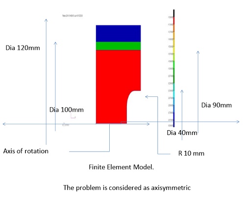
Figure 2 shows the boundary conditions, where the left side represents the base of the die to be placed on the forging press bed, while the right side represents the top free surface of the die.
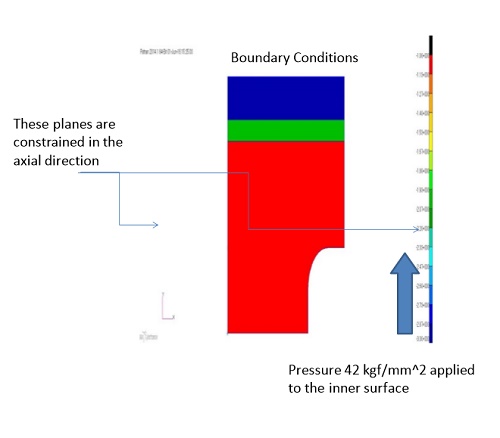
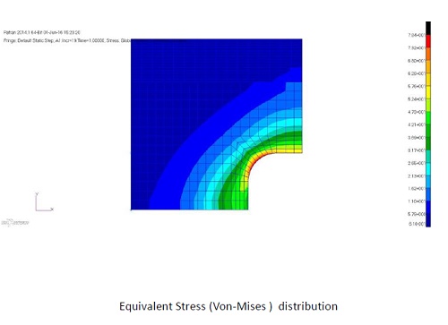
Figure 3 down here shows stress concentration in the radius,
of about 78 kg/sq. mm ~ 111ksi ~ 765 MPa.
It is not negligible, but inconsequential for this calculation.
In Figure 4, the maximum stress around the corner of the internal ring is found to be
about 6.8 kg/sq. mm ~ 66.7 MPa ~ 9.67 ksi
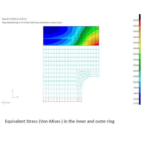
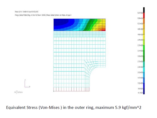
while in Figure 5, down here, in the external ring it is
about 5.9 kg/sq. mm ~ 57.9 MPa ~ 8.39 ksi.
3. Conclusion
This calculation demonstrates that, in the example considered, the external ring can easily bear the maximum stress under forging, as the requirements above are easily satisfied by any suitable construction steel.
Moreover the outermost hot mounted ring, excluded totally from this calculation, should provide ample margin of stability for a long production run.
Further elaboration on Assembly techniques can be found at:
Comments and feedback and further questions are welcome.
Please use the Contact Us Form.

Watch - The Video:
and also
POWERED BY:
![]()
Click on this Logo NOW!
Copyright © 2016
by Elia E. Levi and
welding-advisers.com, All Rights Reserved.