| Back to Back Issues Page | |
 |
|
|
PWL, Issue #015--Dilution, Nb-Ti Joining, Spherical Vessel, Tack Welding, MIG/MAG and more... November 01, 2004 |
|
| We hope you will find this Letter interesting and useful. Let us know what you think of it. Practical Issues, Creative Solutions
This publication brings to the readers practical answers to welding problems in an informal setting designed to be helpful and informative. We actively seek feedback to make it ever more useful and up to date. We encourage you to comment and to contribute your experience, if you think it may be useful to your fellow readers.
You are urged to pass-along this publication to your
Date: November 2004 - Practical Welding Letter - Issue No. 15
-----------------TABLE of CONTENTS---------------
1 - Introduction 2 - Article: Pickup, Dilution and Recovery 3 - How to do it well: Manufacturing a Spherical Vessel 4 - Filler Metal: joining Niobium to Titanium 5 - Online Press: recent Welding related Articles 6 - Terms and Definitions Reminder 7 - Article: Tack welding 8 - Site Updating 9 - Short Items 10 - Explorations: beyond the Welder 11 - Contribution: MIG/MAG Welding 12 - Testimonials 13 - Correspondence: a few Comments 14 - Bulletin Board
1 - Introduction In this issue of Practical Welding Letter we deal with a number of interesting topics a few of which were proposed by readers who were so kind to send us their feedback. We would like to encourage other readers to let us know which subjects would better cater to their needs. Write us. Click here. Pickup, Dilution and Recovery are terms that describe how melting and mixing of elements from base metals can alter the composition of the weld pool and how the characteristics of final weldments are influenced by different interactions. The basic notions will help to understand what is to be expected in any specific case. How to join a Refractory metal to a Reactive one ? (Niobium to Titanium). It may be difficult if fusion welding is attempted. But there are possibly other solutions whose selection depends on application, on requirements and on available equipment. Tack welding is present in most of the setups. There are certain prejudices as to its application and control. It is a subject to consider, especially for dispelling the notion that its quality is not important . We are proud to be able to present to our readers for the first time a real Contribution on Gas Metal Arc Welding from a kind Professional who accepted to share with us his wide experience. Unfortunately the pictures may not be up to the standard we would have liked to see. It is beyond our faculties to amend them as we would have preferred, because we want not to delay this publication. We hope that other new contributing writers will come forward to propose to our readers their writings of wisdom. The Page of the Month added to the Site deals with Refractory Metals, what they are, what they are used for, and how they are joined. Other Departments follow as usual. We would like to point out that an article of ours on Weld Repair was selected for publication by a well known magazine called The Fabricator, and it will be visible online in a few days as announced further down. Let us have your feedback, click here. 2 - Article: Pickup, Dilution and Recovery For equal and homogeneous base metals, welded with a similar, compatible filler metal, the amount of composition change generated by the welding process is not important relative to the final composition of the weld. It may have importance, though, for the characteristics influenced by heat input, like cooling rate and transformation products. Different materials are selected and must be joined together whenever different portions of a structure are subjected to different service conditions. If there are composition differences, those may show up differently in the weld metal. Pickup is the increase in the proportion of any of the alloying elements in the weld deposit due to melting of some of the base metal. This is the case when the filler metal has less of an element than the base metal. The amount acquired in the melt depends on process and actual parameters. It may be used to advantage to give certain desired properties to the weld metal. Conversely, Dilution is the reduction of alloying elements in the melt, relative to the amount present in the filler, due to mixing with leaner base metal. Dilution, expressed as a percentage, represents the amount of fused base material with reference to the total amount of molten metal (base metal melted and filler metal added) in the weld. When the chemical composition of both base and filler metal is known, the weld metal average composition can be calculated if the amount of dilution is known. Given the original section of the joint, experimental determination of dilution can be based on area measurements on a transverse cross section through a test weld. Dilution is affected by the welding process employed and by the actual parameters (essentially current density and polarity, welding speed, thickness and technique) used, which influence the amount of penetration achieved. Recovery in percentage represents the amount of any element present in the weld metal, relative to the amount of that element in the filler metal. Recovery may be near 100% for elements that are transferred totally to the weld, or it may be a small fraction if they are volatilized or oxidized when the filler metal is melted. In dissimilar metal welding, selection of a suitable filler metal is important for obtaining in the fusion zone an alloy that will perform adequately in service. The filler metal should be compatible with both base metals and be capable of being deposited with a minimum of dilution. The selection of the proper filler metal is not based on matching the chemistry of the base metal. Rather, it is based on matching the weld metal and base metal service properties. It must mix readily with the base metals to produce a weld metal that has a continuous and ductile matrix phase. It must be able to accept alloying by the base metals without producing brittle or crack-sensitive microstructures. The resulting weld metal must also be stable in time under the expected service conditions. A successful weld between dissimilar metals is the one that is at least as strong as the weaker of the two metals being joined, to prevent failure in the joint. For welding an austenitic stainless steel to a carbon or low-alloy steel, the recommended procedure involves first the buttering or covering of the steel edge with one or two layers of type 309 or 310 stainless steel filler metal. The dilution with the mild steel should be kept to a minimum, to avoid martensite formation in the weld metal which may produce cracks. It is important to understand how the dilution of the selected filler metal with the base metal affects the composition and metallurgical balance, such as the proper ferrite level to minimize hot cracking, absence of martensite at the interface for bond integrity, and carbon at a low level to ensure corrosion resistance. Similarly for welding a copper alloy to a ferrous or a nickel alloy one has to control dilution in order to retain ductility. It is common to weld an overlay of a suitable buffer metal on one or both sides of the joint before welding to minimize or eliminate mixing of mutually incompatible combinations. Most of the heat has to be directed toward the copper side because of its greater thermal conductivity. The dilution of a nickel base alloy by a dissimilar metal must be limited. Welding Monel (different types of alloys of nickel and copper) to an austenitic stainless steel with a stainless filler will cause copper pickup from the Monel: the weld metal will then become hot short and it will easily crack. Also a Monel filler cannot be used, because chromium from the stainless steel will dilute the weld metal, again causing cracking. Only nickel or rich nickel alloys could be used, but it is always recommended to qualify the welding procedure with the required tests. The main requirement for selection of filler material is that the weld metal be strong, corrosion resistant and sound, without susceptibility to cracking, which is directly proportional to the amount of dilution. Some problematic combinations to be avoided in the weld metal are:
3 - How to do it well: Manufacturing a Spherical Vessel Q - What is the normal method of manufacturing a welded spherical pressure vessel? A - Assuming quite a heavy wall spherical pressure vessel of large dimensions, the material and the thickness of the plates are to be selected depending upon service pressure and conditions. The vessel will be manufactured by welding together prepared sectors. The dimensions of the sectors will depend upon the size of the press available in the workshop for hot forming the plates in special dies. On the drawing table, (or on the computer screen) the sphere is divided into two hemispheres. Each of them is again divided in four, six or more sectors depending on their dimensions. Two caps shall be located at the poles. One single sector has to be designed in detail: they will all be equal. Some material has to be added at the margins for precision cutting and chamfering after forming and stress relieving. Depending on material, dimensions, process etc., the sectors have to be prepared for welding together once the joint details have been established. If clad material is used (i.e. a carbon steel with a thin layer of stainless steel) special welding procedures must be developed and tested. Inlets, outlets, manholes and whatever passages are needed, are designed to be performed at the proper stage in the process. It is going to be a nice welding project. 4 - Filler Metal: joining Niobium to Titanium A reader reported on having found difficulties in Electron Beam Welding of Niobium (Columbium) to Titanium: "We see on Xray inspection a great deal of stratification across the melt area in reference to density on Xray film, also a huge difference between parts, some appear quite homogeneous, others seem to display a gross high/low density extremely grainy image." The result is not unexpected, due to the great differences in melting points of these pure metals, as follows: Their alloys will show melting ranges approximately of the same magnitude. The difference in melting temperatures of the two metals that are to be joined is important when a high energy density fusion welding process is involved, as one metal may be molten long before the other. Significant difference between the melting temperatures of the two base metals can result in rupture of that having the lower melting temperature. Solidification and shrinkage of the metal with the higher melting temperature will induce stresses in the other metal while it is still in a weak, partially solidified condition. This problem may be solved by buttering, or depositing layers of a filler metal of intermediate melting temperature on the face of the higher melting temperature base metal. The weld is then made between the buttered face and the other base metal with a much reduced melting temperature differential. Buttering may also provide a transition between materials with substantially different coefficients of thermal expansion (CTE) which are subject to cycling temperatures in service. Or a barrier layer that will slow the migration of undesirable elements from the base metal to the weld metal during postweld heat treatment or in service at elevated temperatures In fact, although acceptable results might occasionally be achieved, fusion welding of this particular (Nb-Ti) dissimilar metals combination is strongly not recommended. Depending on the purpose, on the exact alloys selected and on the design of the part, alternative joining method should be explored, all having potential of producing strong joints resisting even at high temperature. Besides solid state joining processes like diffusion bonding, that may require equipment and methods possibly not readily available, and friction welding, that depends on the geometrical configuration of the joints, brazing is the recommended process to explore. There is quite a long list of possible brazing filler metals available as foils, to select from, depending on the actual service of the part. One recommended brazing alloy has the following composition: Ti - 11%Cr - 13%V - 3%Al. Titanium alloys with vanadium, or with vanadium and tantalum, or titanium with chromium and also pure vanadium are among the suggested alloys. Although not all the filler metal alloys that were laboratory tested and studied for brazing may be readily available in commercial quantities, nonetheless the manufacturers of these alloys, given the details of the application sought for, should be able to help in the selection for the intended service conditions.
5 - Online Press: recent Welding related Articles An article on Weld Repair will be visible online after Nov. 9 at Vertical Welding Double Electrode Improve GMAW Digital Radiography Using Weld Gauges
6 - Terms and Definitions Reminder Buttering is a welding procedure whereby a deposit of a different metal or alloy is laid down on a base metal to provide a metallurgical compatible material for the completion of welding of dissimilar alloys. Hot Wire welding is a process using resistance heating of the filler wire by current flowing through it while it is fed into the weld pool. Joint efficiency is the ratio of tensile strength of a specimen containing a joint to the strength of the base metal, expressed in percent. Kerf is the gap produced by a cutting process with material removal. Mechanized welding is any process where the torch or electrode are mechanically held in proper position against a joint in relative movement. The equipment needs constant operator assistance in response to visual observations to correct for occasional drift or improper operation. Toe of weld is the border between the face of the weld and the base metal Vertical up or uphill welding means producing a weld in vertical position with progression in upward direction. Vertical down or downhill welding means producing a weld in vertical position with progression in downward direction .
7 - Article: Tack Welding Tack welds are temporary means of holding components in proper alignment until the final and definitive welding is completed. The "temporary" character of tack welds may give the false impression that the quality of these auxiliary joining aids is not important and that this operation need not be properly programmed, performed and inspected. This is not true.
Furthermore tack welding must not interfere with final welding and must not degrade its quality. It must not introduce weld defects like arc strikes, craters, cracks, hard spots, or slag left in place. Therefore most Codes require that tack welding be performed only by welders fully qualified in the weld procedure used for the finished weld. The requirements are applicable for any welding process used. In general, but not necessarily, tack welding is performed by the same method that will be used for the final weld. Electron Beam Tack Welds, performed with reduced power, are used to supplement or replace fixturing and to keep correct shape and dimensions during final Electron Beam welding. Aluminum alloy assemblies to be joined by friction stir welding are tack welded by the same process with a small tool developed for this purpose. Tack welding has to keep in place the elements and to resist the considerable force, not sufficiently contrasted by clamping devices, that tends to separate the components. In all fusion weld processes, the sequence and the direction of the tack welds is important for distortion control. For a long seam tack welding should start at the middle and proceed towards the free ends, alternatively in both directions. Besides maintaining the joint gap tack weld must resist transverse shrinkage. Tack welding is a decisive stage in the preparation of pipes for welding. Thorough attention should be given to obtain adequate and consistent root opening (joint gap), that controls the success of the most important root pass. Although this work could be assigned to fitters, it should be closely supervised to make sure that the workforce involved is properly qualified. Number and size of tack welds depend on pipe diameter and wall thickness. Tack welds with complete fusion should be of the same quality as the final weld. All the tack welds must be thoroughly cleaned before proceeding with the weld. In any case, irrespective of fixed or rotated position and of direction (vertical down or vertical up), both ends of each tack weld must be ground to present a very gradual slope and to blend its sides into the bevel. When tack welding is used as fixturing for brazing, the area surrounding the tack must be thoroughly cleaned from oxides developed during welding. In manual welding operations tack welding may be used to set up the workpieces without the use of fixtures. In semiautomatic or automatic welding however, the meeting points of final weld electrode with tack welds may impair control of arc voltage and of filler wire feeding so that manual assistance is specially important.
8 - Site Updating 8.1 - This time we announce the publication of a new page on Refractory Metals: it gives a review of their most important characteristics and use, besides providing basic information on joining and welding. If you order special furnace trays made of molybdenum for elevated temperature service, it helps to know that they can be used only in vacuum. If you wish to see the page, click here. The Site Map outlines both old pages and new additions. 8.2 - As promised last time we present also a Downloads page, wherefrom useful information can be obtained at no cost, in the form of well written e-books that provide not only insight and understanding, but also the drive to start in new directions. We strongly recommend that you visit that page. And that you download (by clicking on the Download button on the NavBar of our Site) those free e-books that meet your interests.
9 - Short Items 9.1 - Roll cladding and welding: Several systems of different materials in sheet form bonded together with a rolling process are available for a great variety of applications. Adequate ductility is an important requirement for both the components and the composite. Bimetallic strip for thermostats, coining alloys, corrosion protective clad layers bonded upon substrates are only a few of many uses. In general the composite metal has a thin sheath of valuable material selected for its particular properties, bonded upon an inexpensive substrate that provides support and cathodic protection, corroding sacrificially Roll welded heat exchangers with flow tubes integrally built in the thickness of the composite are widely diffused. The different metals are thoroughly cleaned with chemical and mechanical means and then rolled together at room temperature or under heat, depending on their nature. Total thickness reduction may be about 80%. A final annealing heat treatment may be used. Alclad aluminum is the largest application for hot roll bonded materials. A more active aluminum alloy is bonded to a more noble aluminum alloy. In service, the outer clad layer of aluminum corrodes sacrificially and protects the more noble aluminum substrate. 9.2 - Temper bead procedures. It is known that the Heat Affected Zone of a single-pass welded steel, displaying grain-coarsened structure is normally the region having the lowest toughness. In multipass welding, subsequent weld deposits provide some reheat treatment to previous beads. The microstructures of these zones changes locally to different morphologies depending on the peak temperature reached and its value relative to the critical points Ac1 and Ac3. Application of this knowledge is specially meaningful when confronted with repair of important structures. After repair, a repetition of the Post Weld Heat Treatment (PWHT) that was originally performed is usually not feasible. It was used to temper the hard regions in the Heat Affected Zone and to relieve residual stresses. Arc heating of subsequent beads can then be used successfully to achieve the tempering function of PWHT by suitable spatial positioning and sequencing of the individual passes. Grain refinement in the HAZ is also required to increase the toughness and thereby offset the harmful effects of residual stresses that would remain in the absence of PWHT. The exact procedure development must be supplemented by mechanical testing and needs qualification by actual toughness determination of welded specimens. 9.3 - Inclusions. Nonmetallic inclusions are impurities that are deleterious to physical, mechanical, electrical, and aesthetic properties. Some may be present in the metal from the original manufacturing processes. Other imperfections like slag inclusions and oxide inclusions may be introduced inadvertently by certain welding methods as solid materials entrapped in weld metal or between weld metal and base metal. Slag inclusions are nonmetallic materials formed by the slag reaction that are trapped in the weld. Entrapment can occur when slag becomes mixed in the weld pool or when surface slag is not completely removed and is covered by subsequent weld passes. In rolled carbon steel plate, the presence of flattened inclusions (called laminations), such as silicates or manganese sulfides, can cause difficulties, particularly in welding T-joints. The cooling stresses may cause rupture by decohesion between the inclusions and the steel matrix, producing a fracture with a laminated appearance called lamellar tearing. Acceptance criteria depends on the inspection method and the effects of the discontinuity on service fitness. The existence of slag inclusions in shielded metal arc welds is usually not critical if it is located deep in the metal. However the presence of nonmetallic inclusions at or close to the surface is detrimental, because inclusions can act as stress raisers, initiators of fatigue cracks. Slag inclusions between weld beads reduce the strength of the weld. The structural importance of the presence of slag inclusions in a weld is evaluated in terms of their size, shape, amount, distribution, and location. Tensile strength of the weld is reduced in proportion to the projected area of the slag; yield strength is affected to a lesser extent. Tensile ductility is reduced appreciably. Metallic inclusions are mainly tungsten bits falling from electrodes in the weld, following inadvertent welding procedures. They are readily visible through X-Ray inspection as dark (more dense) spot indications. 9.4 - Gleeble Testing. The Gleeble, a thermomechanical testing device, has been used in a wide range of applications involving study of a variety of material problems. The Gleeble system permits simulation of virtually any thermomechanical process. The system is built to:
The Gleeble is a fully computer interfaced system, readily programmed to provide reference signals for closed loop control of both thermal and mechanical operations. In particular for welding related research it has been used in studies of:
A major advantage of the Gleeble is that it generates large volumes of microstructures that simulate small, hard-to-study regions in actual weldments. The Gleeble has a long and proven history as a tool for both the study of metallurgical phenomena at the research level and for materials testing to predict service behavior at the production level. The device is used in a variety of applications in the metal industry and is in no way limited by its historical application to welding. 9.5 - Vibrational Stress Relief after welding is a common alternative, preferred to the more generally diffused Thermal Stress Relieve in case this one is particularly cumbersome due to physical dimensions of the part or its emplacement, or when heating is forbidden because of conflicting requirements. One disturbing fact is that VSR has not been approved to date by accepted codes for pressure Vessels and Pipes in spite of its recorded successes. This is probably due more to difficulties inherent in the documentation of an effective vibrational treatment having been performed, than on the demonstration of the validity of the results. Conversely a simple record of thermal cycles in a given furnace is all that is needed for documenting TSR. Residual stresses present in weldments are due to shrinkage strains developed during cooling from elevated temperature, augmented sometimes by morphological transformations of metallurgical phases involving a change of volume, as happening sometimes in welded metals. The risk is that those stresses summed to external ones, exceed the fracture limit of the metal in cause, causing cracks and rupture or reduce the resistance to fatigue. Thermal stress relief permits a significant decrease of peak stresses, by reducing yield strength and creep strength of the material at elevated temperature: this fact permits limited local metal flow, resulting in microscopic (sometimes even macroscopic) adjustments broadening and diminishing the residual stresses. This is a typical stress-relaxation behavior. A different method uses mechanical peening of the weld either by hammering or by shot peening equipment: this is done sometimes on tool steels and other materials immediately after welding and before cool down. Vibration waves imposed upon a solid introduce energy in the finest atomic structure, permitting local movements and adjustments normally forbidden in a cool structure at rest. With properly conceived set ups that insulate the structure from the surroundings, usually on rubber pads, one can succeed in reducing residual stresses. Vibrations are generated within sturdy vibrators with speed regulation, variable unbalance, capable of speeds that can resonate the components involved. Instrumentation should be capable of tracking all changes. There is a discussion if the frequency of vibration to be preferred is that inducing resonance in the structure, with the largest movements (which may risk to cause damage), or if a sub resonant (or subharmonic) frequency should be used. Vibration works to reduce residual stress by localized plastic deformation. The material deforms to accommodate the resulting stress augmented by the vibratory energy and the residual stress diminishes. For specimens the demonstration of the successful stress relaxation can be provided either by non destructive X-Ray Diffraction measurements, able to find interatomic distances and microscopic distortion, or destructively using strain gages bonded to metallic surfaces. Strain gages are made of an extremely thin, small, strain-sensitive electrical resistor bonded to a flexible backing material that, when adhesively bonded to the structure or test part, transforms surface strains into changes of electrical resistance, directly measurable and translatable in units of stress. By measuring the original condition of a system of strain gages and again its status after cut up of the specimen (when the residual stresses are relieved), one can determine the relaxation intervened, permitting the reconstruction of the stresses that were present at the start. On this subject see: http://www.aws.org/wj/sept01/cullison.html http://ceer.alfred.edu/research/vibratory.html 9.6 - Proof testing is used for demonstrating the capability of a structure to stand up to design loads. Proof testing is simply a "proof of the cake". It can be a contractual or a code requirement, but it can be implemented in many cases for a structure or for a component to check the actual performance at full load. This generally refers to static loads, be it for a pressure vessel or for a hoisting device. Pressure vessels are usually filled with a liquid (although they may be designed to contain a gas) and then submitted to the required pressure. On top of that it is customary to give hammer blows on the exterior, to produce a pressure surge that will show and enlarge any possible leaks. More often than not the design full load is exceeded on purpose, say by ten or twenty percent, to verify that an accidental overcharge will not destroy the construction. Of course there must be also an assurance that this testing itself will not initiate an unintentional damage that will weaken sensitive spots. For important constructions occasionally exposed to cold temperatures, it is imperative that the minimum temperature at the time of testing be specified by the designer. Proof test must be followed by an accurate visual inspection to find out possible signs of dangerous indications or unacceptable deformation. 10 - Explorations: beyond the Welder Low Cost Titanium Slabs Tools for Nanotechnology Mini Human Species Cassini Closes in on Titan Measuring Package Performance
11 - Invited Contribution: MIG/MAG Welding
You may be more familiar with the term MAGS (Metal Arc Gas-Shielded) welding or even C02. In the USA it’s known as GMAW (Gas Metal Arc Welding). But, to be honest this article is not about the use of terms, providing of course, we all understand I am talking about Metal Inert/Metal Active Gas welding, commonly referred to as MIG/MAG welding in the UK, even though the most common gases are a mixture of argon and CO2, rather than just CO2.
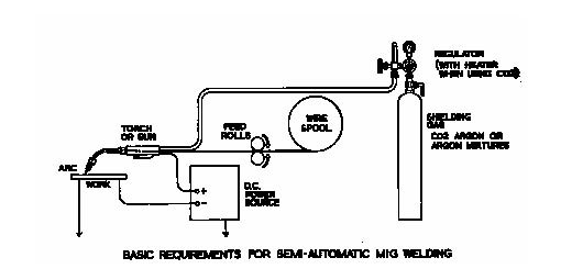
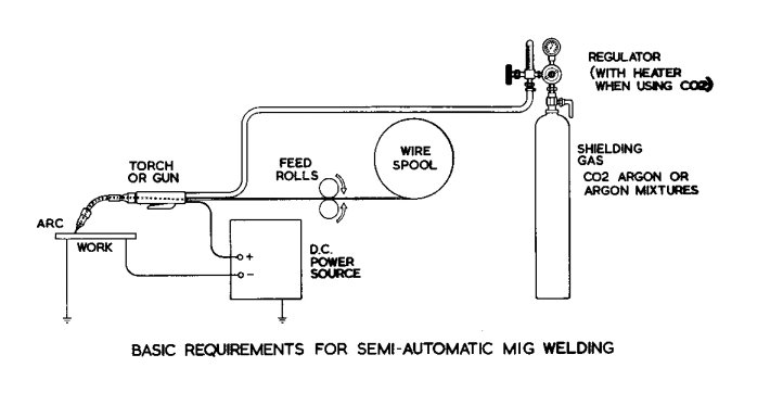
Semi-automatic welding consists of a DC arc burning between a thin metal wire electrode and the workpiece. The arc and weld zone are enveloped in a protective gas shield. The wire is fed automatically from a spool, through a torch, which is connected to the positive terminal and is moved by hand.
Now that we have got this out of the way, what I really wanted to discuss is where this process fits into today’s industry and what problems, if any, we are now seeing. You certainly don’t have to be a welding expert to know that in every fabrication shop up and down the country at every level, from DIY to high-tech, the MIG welding process is there, and for very good reasons. MIG has all but replaced Manual Metal Arc (MMA) welding, and in a fabrication environment has completely replaced oxyacetylene welding in all but in the smallest of vehicle body shops. It’s probably fair to say, in its simplest form, it hasn’t totally replaced MMA welding where pressure vessels are concerned. Although in its high-tech form ‘synergic’ the process provides solutions to some of its weaknesses, more about these in a minute. Synergic in simple terms may best be described as ‘pulsed’ current control.
So what’s the problems with the process? Actually there is nothing technically wrong with the process at all, other than it may be too easy to use! It’s more of a problem with the state of our industry and the demise of fully skilled/trained welders. The MIG welding process clearly offers some major advantages over MMA, not least of which is a massive increase in productivity and yes, it is easier to initially learn and to use.
Because the process is ‘semi-automatic’ it does mean in less experienced hands the potential for weld defects is actually increased. This is due to it being easier to operate, or at least it appears that way. But is it?
This is a large part of the problem. In real terms producing high quality welds by MIG welding should be no easier than any other welding process, but because the operating parameters and controls for the machine are easier to select/control the process can provide the illusion of creating a successful weld, when the reality may be quite different.
Personnel employed in one discipline are often asked to master several, usually without the benefit of formal training. Because of MIG weldings undoubted benefits, the process is the only sensible solution when it comes to mass-production as well as maintenance and fabrication environments. However, it is these very benefits that are now affecting industry, through an increase in weld defects, which tend to go unnoticed until a failure occurs.
On our travels up and down the country we see more and more problems with MIG welding than any other process. Out of all the welds or welders we test, MIG welding has the highest failure rate and when it comes to a typical ‘T’ joint fillet weld test, I would go as far to say only 20% of the welders we test are able to ensure adequate root fusion is produced on a first attempt. We believe in part, this is due to it being considered as a semi-skilled method. Also, in part, by an increased tendency for MIG welding to be susceptible to certain types of weld defects, i.e. lack of fusion and cold lap are common.
With a small diameter wire you can weld thin gauge metal, or thick steel plates/pipes in any position and do nothing but flick a couple of switches and adjust the wire feed speed! If the same person were asked to make a weld using MMA, in the same training period, it would be most unlikely they would succeed. This is because the only variable a MMA power source provides, is current. Get that wrong and the results will be poor. Whereas MIG welding, being semi-automatic, controls voltage and wire feed speed automatically thereby, controlling arc length/burn off.
For all fabricators where MIG welding is used it’s fair to say 8-10 of the welders employed will be self-taught or at best semi-skilled on that process. The real knowledge and ability of many MIG welders is frighteningly poor, daft as it sounds, this is probably due to the ease and popularity of use. If you speak to any skilled welder, he will always tell you he avoids MIG welding, if possible! This ‘semi-automatic’ principle of operation doesn’t mean the process is semi-skilled; it refers to the control of welding parameters that would otherwise have to be controlled by the operator. The result being, the machine will accommodate an inappropriate, or less than ideal setting, thereby, permitting a weld to be made. Whereas, the other welding processes mentioned provide nothing to the operator other than a value of current (amps). It’s the skill of the operator who then produces the weld.
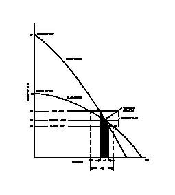
Let me explain a little further. The graphs below show two completely different welding power source characteristics. A ‘drooping’ characteristic, or constant-current output, typical of MMA/TIG welding and a ‘flat’ characteristic or constant-voltage output typical of semi-automatic welding.
As you can see there is no similarity.
With the drooping characteristic you can see a small change in arc voltage produces a much smaller change in arc current, depending upon the open circuit voltage (OCV). This means the burn-off rate is much slower for MMA welding, or put another way, for any given change in arc length the current change is small. This allows manual welding to take place, as even in the hands of a skilled welder, arc length will vary as welding is progressed, but under these circumstances the current changes will only be small. As current is the only controllable variable the welder can set, it’s essential this remains as close as possible to the value selected.
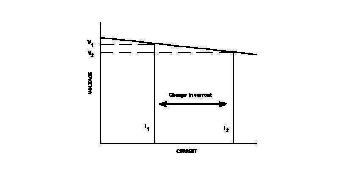
With the flat characteristic you can see a large change in current for a small change in voltage. Because of this, the power source controls arc-length. If this were left to the welder, as in MMA, the change in current would be so large it would not be possible to produce acceptable welds. Therefore, in all semi-automatic welding the arc-length and the ‘burn-off’ rate are controlled by the machine.
The burn-off rate increases as the arc-length decreases so as to rapidly compensate for the increase in current from I1 to I2. This response rate needs to be extremely rapid. Of course the welder needs to try and maintain a consistent ‘stick-out’ length. Stick-out length may best be described as the distance from the contact tip to the work piece.
At the end of the day, because MIG welding is easier to control, it is easy to master in a shorter period of time. This means training courses don’t need to be lengthy affairs, but massive improvements can be seen in under a day for anybody currently engaged in MIG welding who may have never had the opportunity to be trained.
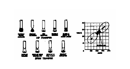
Do you know how many methods of transfer MIG welding provides? Do the terms 'dip', 'globular', 'spray' or 'pulsed' mean anything to you? Are you familiar with the term ‘inductance’ or ‘choke’? How is amperage selected for MIG welding? What are the settings on the front panel on a MIG machine controlling? Do you always get high levels of spatter when welding? What gas flow rate should be selected? What is the importance of the contact tip and weld quality? How do you need to set the feed roller pressure?
These are just a few basic questions. If you cannot answer these or are not familiar with the terms the chances are you are not operating the process to its best potential and weld defects, or at least poor productivity, will be inevitable.
Dip transfer, also known as short-circuiting, is carried out using currents below 200 amps and below 24 volts. Under these conditions the arc is so short that the molten globules at the electrode tip ‘short-circuit’ to the workpiece at rapid, regular intervals. The current during short-circuiting melts off the electrode tip and allows re-establishment of the arc. This is ideal for welding on thin gauge materials and out of position working and/or root runs for butt welds.
Inductance controls the rate of rise up to peak current during dip transfer. Without the correct setting it will cause globules to explode out of the arc resulting in excessive spatter. Too slow a current rise will result in stubbing or starting problems. The higher the inductance the lower the speed at which the short-circuiting current builds up. A low inductance setting will give higher short circuiting frequency and a relatively cold weld. High inductance will give lower short circuiting frequency and a relatively hot weld due to longer arcing periods between short circuits.
The actual amperage in MIG welding is controlled by the wire feed speed. The faster the speed the higher the amperage draw.
In setting up the machine, you are actually setting the voltage, which needs to be in keeping with wire speed feed. Once the wire feed speed and voltage are set the circuit may be 'choked' to produce the correct arc condition.
Spray transfer operates at over 250 amps and over 25 volts. The metal is transferred across the arc in free flight droplets in the form of a fine spray. This transfer is limited to flat/H-V positional welding for steel, due to the large liquid weld pool but will provide a high deposition weld-metal deposit. This means it’s limited to thicker materials.
Gas flow rates will depend on the worksite conditions and to some extent the work to be welded. If we assume you are using a mixture of argon and C02 you should set a flow rate of between 12-18 ltrs/min. The shroud will also need to be kept clean as this also affects gas flow. Tool high or low a pressure and porosity will occur. The contact tip is another important consideration. This does get damaged easily and is essential to good electrical contact, as it transfers current to the wire. Therefore, a worn tip will present all sorts of electrical contact problems. The feed roll pressure is another factor often overlooked as not being particularly important, as is the drum break. If pressure is too high it will deform the wire and cause poor current pick-up, too little pressure and the wire will misfeed.
If we consider all the possible shortcomings discussed so far, it’s not that surprising that weld defects and failures occur. The good news is, to train welders so they better understand the process and can select the correct welding parameters is a quick and simply affair.
If you would like to improve your skills, productivity, quality and costs. Please contact Speciality Welds Ltd, or visit our website at www.specialwelds.com
Tel: 01274 879867
David J. Keats Dip.Eng.,L.Eng.,Sen.M.Weld.I
12 - Testimonials From: horacio navarro 'hnavarro_59@yahoo.com.mx' Hi Elia, Best regards
From: "Toothman Timothy MSgt 178MXS/MXMFM 346-2314" 'Timothy.Toothman@OHSPRI.ANG.AF.MIL>' Thank you very much for your thorough and timely response. Tim
13 - Correspondence: a few Comments It seems that most of the comments have already been published before, but we keep receiving unfocused questions upon too broad ranges of materials, with the misleading inquiry: "What is the best process for..." In these cases my standard answer would be as follows: In any specific case one can try to find The problem is that possibly the inquirer has no specific case in mind and may think that a general question should bring a general answer. The only logical answer possible would be: "it depends..." So, keep asking but try to put focus in your questions, and possibly give a hint on what you are going to do with it and why would an answer be important to you.
14 - Bulletin Board 14.1 - The Weld Academy of the American Welding Society announces new training delivery to the welding industry. The online training distributed on the Internet by WeldAcademy is designed to help students prepare for testing and certification as Certified Welding Inspectors (CWI). See details at 14.2 - As announced last month, the process of presenting on our Site most of the valuable freely downloadable e-books offered by SiteSell.com, our Website Host, has been completed. The Downloads button from the NavBar brings you to the page wherefrom you are linked to the single titles.
See you next time.
Copyright (c) 2004, by Elia E. Levi and welding-advisers.com, all rights reserved |
|
| Back to Back Issues Page |
 A more accurate term might be described as ‘semi-automatic’, meaning the arc is ‘self-adjusting’. Any variation in the arc length produces a change in the ‘burn-off’ rate allowing rapid re-establishment of the original arc length.