| Back to Back Issues Page | ||||||||||
 |
||||||||||
|
PWL#045 - Electron Beam Melting, Welding different Carbon Steels, Filler Metal Specifications, more. May 01, 2007 |
||||||||||
| We hope you will find this Letter interesting and useful. Let us know what you think of it. PWL#045 - Electron Beam Melting, Welding different Carbon Steels, Filler Metal Specifications, Welding Qualification, Welding Effects of S Content on Stainless Steels and more... This publication brings to the readers practical answers to welding problems in an informal setting designed to be helpful and informative. We actively seek feedback to make it ever more useful and up to date. We encourage you to comment and to contribute your experience, if you think it may be useful to your fellow readers. You are urged to pass-along this publication to your friends, if you like it, and if you want to help them. If you received this from a friend and if you like what you read, please subscribe free of charge and you will also receive a bonus book on Practical HARDNESS TESTING Made Simple.
1 - Introduction 2 - Article: Electron Beam Melting 3 - How to do it well: Welding together different Carbon Steels 4 - Filler Metal Specifications 5 - Online Press: recent Welding related Articles 6 - Terms and Definitions Reminder 7 - Article - Phased Arrays of Ultrasonic Transducers 8 - Site Updating: Welding Qualification 9 - Short Items 10 - Explorations: beyond the Welder 11 - Contribution: Welding Effects of S Content on Stainless Steels 12 - Testimonials 13 - Correspondence: a few Comments 14 - Bulletin Board
1 - Introduction We open this 45th issue of Practical Welding Letter with a short note on Electron Beam Melting, a technique recently applied to Rapid Prototyping, an increasingly demanded capability needed to shorten the time from concept development and design to testing and trying. We then answer to a correspondent who asked on the problems of welding together a low carbon to a medium carbon steel. (Note: The correspondent could not see our answer. It bounced back because his Inbox was full...) We continue with an exposition of Filler Metal Specifications. For more complete global reviews and comparisons one should probably look into AWS publications. The application of Phased Arrays of Ultrasonic Transducers cannot be ignored any longer by those actually involved in weld inspection by ultrasonic methods. Our presentation may help as an orientation and as a starting point for deeper research. We are glad to be able to offer to our readers that will hopefully appreciate the opportunity to learn important knowledge, an original Contribution by a kind correspondent, Dr. Timothy Volin. The article deals with the effects of Sulfur content, even in minute amounts, on welding of austenitic stainless steels. Readers capable and willing to share with us their experience are invited and welcomed to join in and send us their Contributions. The other departments are at their usual places. We hope you will enjoy this reading. What about letting us know about your comments? Click on Contact Us. Don't miss..., at the bottom of this page, to watch the 3 minutes SBI! TV Show. It is engaging, powerful, emotional...
2 - Article: Electron Beam Melting The subject of this article may remind to our reader a technology that was reviewed in these pages not long ago: see PWL#043. It dealt with advanced means for repairing expensive parts by Laser Fused Material Deposition. The Electron Beam is similar to the Laser Beam in that it provides concentrated and focused energy usable for welding, melting, drilling and additional purposes. The main differences between the two sources and their derived processes are highlighted in our page on High Energy Welding Processes. Electron Beam in suitable furnaces has been used for melting and refining of metals in vacuum, in the production of nickel base superalloys, specialty steels, refractory metals like tantalum, niobium, very pure tungsten and molybdenum especially for the electronic industry, and reactive metals like hafnium, vanadium, zirconium, titanium and their alloys. Conventional and less common metals and alloys like rare earth alloys, intermetalllc materials, ceramic and uranium are melted by research facilities to develop new grades or to purify them. Purification is done by removal of volatile elements in the material or by distillation and degassing. Electron beam melting is a surface heating method producing only a shallow pool. The methods employed include Drip Melting, Cold Hearth Melting and Refining. Button Melting serves for cleanliness evaluation especially of superalloys. Recently Electron Beam Melting has been applied as a Rapid Prototyping and low volume production method of full density free forms of Titanium and its alloys. Using precise localized melting of evenly distributed metal powder, parts are built layer after layer according to computer controlled scanning patterns. Due to the properties of electron beams that can be instantly deflected by electromagnetic coils without any moving mechanical parts, the scanning speed is very high, so that the process permits fast building rates, of the order of 60 cm3/hour (= 3.7 in3/hour). Full density and fine grain structure produced by this progressive (layer by layer) process (quite different from bulk melting like casting) provide mechanical properties similar to those displayed by wrought metal. Economy of production reflects the flexibility of the process, permitting the manufacture of complex, hollow, intricate parts with the same ease by which simple parts can be made. But the most appealing feature of the process is probably the short time from design to prototype, permitting quick testing and evaluation of new parts. Presently available equipment limits the maximum build size of parts within 200x200x180 mm (7.9x7.9x6.3 in). An article describing this technology was published at page 45 in the March 2007 issue of Advanced Materials & Processes, an ASM International publication.
3 - How to do it well: Welding together different Carbon Steels Note: This is an actual question from a correspondent. Q: I wish to weld different materials, ASTM A-36 and AISI 1045. A: It is not the strength level but the carbon content of AISI 1045 that may make problems. 4 - Filler Metal Specifications Filler Materials were standardized in different countries according to different requirement of local industries. The AWS Specifications for Filler Metals are a useful reference in the United States and wherever they are accepted. Our readers are urged to see the Complete AWS Publications Catalog for 2007, downloadable at no cost from The List of AWS Filler Metal Specifications by Material and Welding Process appears at page 26 of the said catalog. The ordered list of AWS A5 Filler Metal Specifications is there at page 27. Furthermore at page 26 one can find also the following: ANSI/AWS A5.01-93(R1999) AVAILABLE SOON: A5.02/A5.02M:2007 AWS FMC-2000
IFS:2002, International Index of Welding Filler Metals Classifications User’s Guide to Filler Metals European Filler Metal Standards are listed hereafter: BS EN ISO 18273:2004 DIN 1733 DIN 8555 EN 12070 BS EN 12071 EN 12072 EN 12073 EN 12534 BS EN 12535 BS EN 12536 BS EN 14640
EN 14700 EN 1599
BS EN 1668
EN 18274
BS EN 440
BS EN 499
BS EN 756
BS EN 757
BS EN 758
BS EN ISO 1071
BS EN ISO 14172 - DIN EN ISO 14172 - ISO 14172 - ISO DIS 14172 - ISO FDIS 14172
BS EN ISO 2560 - DIN EN ISO 2560 - DS/EN ISO 2560 - ISO 2560 FRENCH Furthermore the following partial list of Specifications of Aerospace Series of Filler metal for welding Rod or Wire and Rod is reported: EN 4324:2002 Aluminium alloy AL-W42201. 5 - Online Press: recent Welding related Articles From The Fabricator: From TWI: From AWS:
6 - Terms and Definitions Reminder Crater Crack is generally a multiple, star-like crack radiating in various directions from a central point in the end depression, called crater, on the face of an improperly terminated weld bead. Face Crack appears on the weld face or exposed surface of the side from which the weld was made. Heat Affected Zone Crack concerns cracking in the not-melted region whose microstructure and properties were altered by the welding heat. See also Underbead Crack. Longitudinal Crack displays its longest dimension approximately parallel to the weld bead axis. Root Crack starts at or near the base metal at the portion of the joint where the members to be joined approach closest to each other. Root Surface Crack appears on the exposed surface of a weld opposite to the side from which the weld was made. Transverse Crack is that whose major dimension runs across the axis of a weld bead. Underbead Cracks occur in the heat affected zone of steel welds under the concurrent presence of a susceptible microstructure, stresses and hydrogen.
7 - Article - Phased Arrays of Ultrasonic Transducers A long time ago, an important European manufacturer of steam turbines received a massive casting from a steel foundry. The cast part was in the shape of an open drum with an integral shaft opposite to the opening. It was to be machined and then welded to a similar part, to become eventually the rotor of a huge turbine. The young technician in charge of ultrasonic testing rejected the part, having found the signs of unacceptable internal porosity. Management officials of both foundry and company were quickly called in, but they could not agree on who was to foot the rejection bill. The dispute was solved with a bet on the quality of the casting. The part was to be cut across the questionable volume (A Salomonic judgement...). The destruction of a sound part was to be paid by the purchaser, while the foundry would take back the fragments and the complaints if defects were revealed in the section. The end was that ultrasonic testing results were correct and the unacceptable defects were indeed displayed. The foundry was then quick to set up their own ultrasonic testing facility that had not been considered a priority until that time. Amazing progress in ultrasonic testing emerged during the decades since then. One of the most important recent techniques came about with the development of phased array transducers. The technology was probably the spin out of innovations introduced by radar and similar antennas without moving parts. Scanning of large areas is performed by manipulating the beam direction through concerted timing of individual emitting sources. The same principles are applied to arrays of insulated piezoelectric transducers arranged in specific patterns and individually wired. Each elemental transducer is excited sequentially by electronic scanning according to precise timing. The phase difference in the triggering of different crystals determines the angle of propagation of the ultrasound composite beam and the focal distance. The functions of focusing the beam, of sweeping it through various angles and of scanning a given volume are all dependent on the electronic control achieved by computer programming. The use of ultrasonic transducers phased arrays represents a major improvement over classic inspection by single probes, as it permits performing scanning at different angles in rapid sequence according to suitable programming. In general phased arrays scanning can be performed at higher speed than with traditional systems, the flexibility to address special problems is greater, imaging of different sections is possible, scanning according to various wave modes and angles is readily achieved, and all data can be stored for later analysis. There are some limitations to this method, but the most disturbing one is possibly the scarce availability of skilled operators. Specialized training has to be provided to prepare adequately the required inspectors. Inspection of welds can be advanced significantly by thoughtful introduction of ultrasonic phased arrays techniques. The following articles, available online, offer additional insight. Phased Arrays for Weld Inspections A New Solution for Ultrasonic Weld Inspection On the same subject an article was published at page 37 of the March 2007 issue of Advanced Materials & Processes, an ASM International publication.
8 - Site Updating: Welding Qualification The Page of this Month adds a few definitions and provides an overview of the requirements established by Codes and Standards. Qualification is not only a piece of paper. It is the coveted document that provides invaluable assets with new customers and projects. This Website Page lists many documents that provide guidelines and requirements towards obtaining the recognized status. Click on Welding Qualification to see the page. For seeing the titles of all website pages and for reviewing a brief description of their content click on the Site Map. Your feedback is important to us. Let us have it by using the form available by clicking on the Contact Us button from the NavBar of any page of the website. 9 - Short Items Accuracy is the degree of conformity of a measured or calculated quantity to its actual (true) value. Bulk Forming processes are those like extrusion, forging, rolling and drawing, in which the original material is in billet, bar, rod, or slab form. A considerable increase in surface-to-volume ratio in the formed parts occurs under the action of largely compressive loading. Multi-Alloy Aluminum is obtained by a proprietary process that permits continuous casting of different aluminum alloys that make contact without mixing in the same ingot. The sheet products produced by rolling such ingots preserve the original layered structure presenting different properties in the different layers. Alloy combinations can be created that display required properties like strength, formability and surface finish in one sheet at will. See the video display presented as the first item in the next section. Modulus of Elasticity (also known as Young's modulus) is the measure of rigidity or stiffness of a material. It is the ratio of stress, below the proportional limit, to the corresponding strain and is measured by the slope of the stress-strain curve in the range of linear proportionality of stress to strain. Repeatability is the degree to which further measurements of the same quantity or movements to the same position will show the same or similar results. Resolution in mechanical devices is the smallest mechanical step that the device itself is capable of implementing.
10 - Explorations: beyond the Welder Novelis Fusion Video Defending the Galapagos Coping with water scarcity Curbing Emissions won't be Enough Dr. Burch's Case Study
11 - Contribution: Welding Effects of S Content on Stainless Steels by Timothy E. Volin, Ph.D., now retired. Austenitic Stainless Steels such as 316L and 304L are the preferred material for many products used in a broad variety of corrosive exposures. The AISI compositions of these stainlesses specifies a maximum of 0.030 weight percent Sulfur; however several properties affecting the manufacture and applications of these stainlesses can vary significantly over this limited range of Sulfur content. Therefore it is desirable to specify a much tighter control of Sulfur content optimized for specific fabrication processes and product applications. Sulfur has a very low solubility in stainless steels, thus it exists as a Sulfide precipitate of Manganese with some Chromium in these alloys. These precipitates will form pits and other defects on electropolished surfaces. The Manganese Sulfide precipitates improve the machinability of stainless steel; compositions intended for machining have sulfur compositions near the 0.030 weight percent maximum, whereas stainless steels with very low Sulfur levels require lower feeds and speeds and will consume more tooling during machining. The Manganese Sulfide precipitates also reduce the corrosion resistance, as they are preferred sites for the initiation of corrosion, particularly on surfaces not parallel to the working direction of the raw material stock, where the inclusion "stringers" formed by the working intersect the surface. This is termed "end grain corrosion". Sulfur also strongly affects welding of stainless steel; variation of Sulfur from very low contents to the 0.030 weight percent maximum permitted can increase weld bead penetration by approximately a factor of two for similar weld parameters. An example is shown in the following Figures 1a and 1b:
Figure 1a - Weld in 316L stainless steel with 0.025
Figure 1b - Weld in 316L stainless steel with 0.001
The microsections were performed through automatic orbital welds of two samples of 316L tubing. The weld parameter settings were identical for the two welds. Note the significantly decreased penetration of the low Sulfur level sample. The effects of Sulfur are summarized in the following Table.
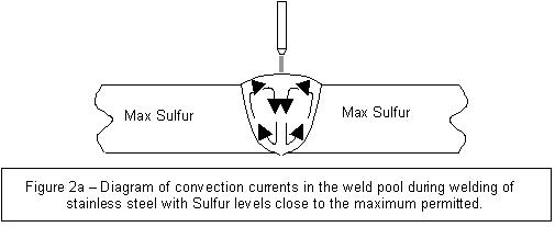
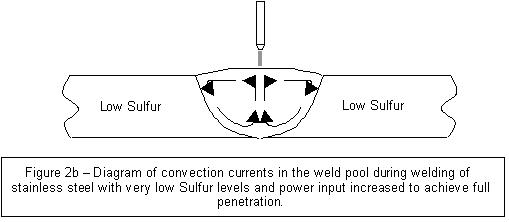
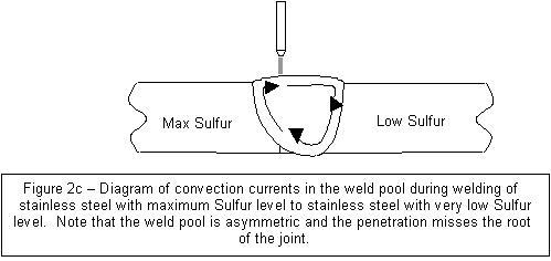
Two effects are observed on welding with variations in Sulfur level: The latter effect is due to a reversal of the convection currents in the weld pool at approximately 0.005 weight percent Sulfur. At Sulfur levels significantly above 0.005 weight percent the convective currents flow downward from the arc, causing deep penetration as illustrated in Figure 2a, whereas at Sulfur levels well below about 0.005 percent the convective currents flow outward from the arc, causing a wider weld pool and shallower penetration as illustrated in Figure 2b2. Serious problems can occur when attempting to weld two pieces of stainless steel with substantially different Sulfur contents. The weld pool can become asymmetric, favoring the low Sulfur side, and cause the root of the weld to shift away from the joint, as illustrated in Figure 2c. In order to minimize this effect it is desirable to match Sulfur contents in components to be welded to within ± 0.007 weight percentage points, or less if below 0.005 weight percent Sulfur. Greater differences in Sulfur contents require very careful weld set-up to ensure full penetration to the root of the joint.
These effects lead to the following recommendations to ensure optimum weld quality when welding stainless steel: 1. Check compositions of pieces to be welded. Match Sulfur contents. References: 1. K. Watanabe and K. Masuda, Effects of Residual and Micro-Alloying Elements on Welding of Stainless Steel; Part 1: Effects on weld pool behavior by GTAW, IIW Doc. IX-1837-96, International Institute of Welding, 1996, 17 pp. (Literature review) 2. Pollard, B., Welding Research Supplement, 202 (Sept. 1988). [Note: The following Reference was added by PWL]. Note: We are grateful to Dr. Volin who kindly sent us this article and obtained for us the permission to publish it for the benefit of our readers.
12 - Testimonials From: McHugh, Timothy (e-mail removed for security) Dear Elia, I find all your articles extremely interesting and helpful. I do in fact retain your letters for reference purposes and at this moment in time I am working on a project [...] as well as the construction of a new Sulphuric acid plant.
regards,
From: "Judy and Ken Mellott" (e-mail removed for security) You are welcome, Elia. Best Wishes, 13 - Correspondence: a few Comments Correspondence is usually an interesting part of the job of running this Website. But unfortunately sometimes the questions are so vague that no useful answer can be proposed. What could I do with the following question? Please send further details." Or with the next one: I would say they are useless, at least. It was somewhat disturbing... ...until I received this message: Arnold said it best..."I'll be Back..."
14 - Bulletin Board 14.1 - 18th Advanced Aerospace Matl's & Processes 14.2 - Explosion of New Processes Conf. From SiteSell:
POWERED BY: Build It!"> Click on this Logo NOW! 3 Minute Shortcut. Click on SBI! TV Show! Copyright (©) 2007, by Elia E. Levi and
See you next time... |
||||||||||
| Back to Back Issues Page |