| Back to Back Issues Page | ||||||||||
 |
||||||||||
|
PWL#130 - Welding at NASA MSFC, Jig improv., Comb. Chamb. F.Metal, Weld. Stainl. St. Stds, Ti Shield June 02, 2014 |
||||||||||
| We hope you will find this Letter interesting and useful. Let us know what you think of it.
PWL#130
Welding Progress at NASA's Marshall Space Flight Center (MSFC), Jig Improvement, Filler Metal for a Combustion Chamber, Helpful Information on Welding Stainless Steels Standards, Laser Beam Welding and Cutting, Bulletin 96 on Molybdenum, Titanium Trailing Shields and much more... DON'T USE REPLY to send your messages! Use the Contact Us form instead. This publication brings to the readers practical answers to welding problems in an informal setting designed to be
helpful and informative. We actively seek feedback to make it ever more useful and up to date. We encourage you to comment and to contribute your experience, if you think it may be useful to your fellow readers. You are urged to pass-along this publication to your friends, if you like it, and if you think it may help them. If you received this from a friend and if you like what you read, please subscribe free of charge and you will also receive a bonus book on Practical HARDNESS TESTING Made Simple. The addresses reported hereafter were live and correct at the time of their publication. There is no guarantee that they will always be so, because they are administered by the sources themselves and are under their control. Note: References to articles or other documents are given here in If they are URL's (Uniform Resource Locator), which is the analogue of an address, they begin with "http://..." or "www.". These are not live and must be copied and pasted entirely into the browser (after having been selected with the mouse or otherwise). If they are long they may be displayed in two or more lines. In that case one has to care that the URL be copied completely in a single line without any space, and Enter. If the information is important to you as we hope, you may save the selected pages in a suitable folder on your Computer for easy reference. You are welcome to forward this page to those of your friends who may profit of this information.
1 - Introduction 2 - Article - Welding Progress at NASA MSFC 3 - How to do it well: Jig Improvement 4 - Filler Metal for a Combustion Chamber 5 - Online Press: recent Welding related Articles 6 - Terms and Definitions Reminder 7 - Article: Helpful Information on Welding Stainless Steels Standards 8 - Site Updating: Laser Beam Welding and Cutting, Bulletin 96 9 - Short Items 10 - Explorations: beyond the Welder 11 - Contributions: Trailing Shields for Welding Titanium 12 - Testimonials 13 - Correspondence: a few Comments 14 - Bulletin Board
2 - Article - Welding Progress at NASA MSFC
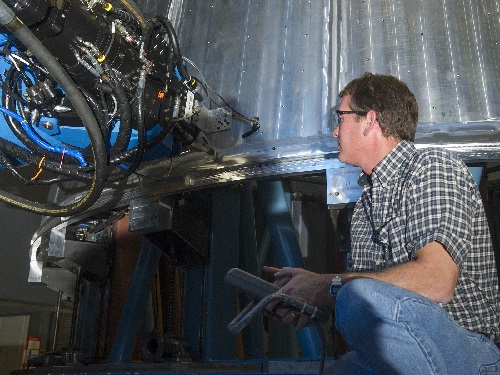
An article published at page 38 of the May 2014 issue of the Welding Journal sheds light on one of the most modern centers of welding development and excellence operating at the forefront of technological advancement. NASA’s Marshall Space Flight Center (MSFC), known as the propulsion research center, has a dominant presence in management, manufacturing and fabrication of spacecraft propulsion systems. The article describes in some detail the evolution of innovations introduced in the revolutionary Friction Stir Welding (FSW), the process invented at The Welding Institute (UK). The self-reacting friction stir welding (SR-FSW) was made possible by the introduction of the dual-shouldered pin assembly, a modification of the retractable stirring tool needed for welding tapered metal sheets, where the thickness changes along the weld. To close out the circumferential SR-FSW welds, MSFC engineers developed friction pull plug welding, as reported in PWL#097, the Issue 97 of Practical Welding Letter for September 2011, section 11, in a note titled Friction Taper Plug Welding. The WJ article describes the evolution of requirements and of equipment employed along the sequence of the projects realized in the course of several decades, and then mentions two new processes that are presently under investigation: thermal stir welding (TSW) and ultrasonic stir welding (USW). The following explanation is reported completely from the above article: "The TSW process decouples the heating, stirring, and forging elements of FSW and allows independent control of each process element. Heating is done with an induction coil and a stir rod protrudes through an upper nonrotating containment plate, and is captured by a lower nonrotating containment plate. The containment plates apply a compressive force upon the plasticized weld nugget material. Since the containment plates do not rotate, they can be shaped into desired geometric configurations." See also: Thermal Stir Welding "NASA’s ultrasonic stir welding process is similar in nature to friction stir welding in that it uses a rotating pin. The heating, however, is not generated via friction but is created by ultrasonic energy instead. Thus, unlike friction stir welding that requires significant forces and countering support, the NASA process does not need reactive tooling and can be used for manual or robotic welding." From: NASA’s Ultrasonic Stir Welding Process The article concludes with the following hopeful remark: "The impact of a large welding center, like the Marshall Space Flight Center Advanced Welding and Manufacturing Facility, is bigger than a first impression might suggest." For a more complete overview of the activities and of the achievements of MSFC, interested readers are urged to seek the original article from the source indicated above.
NASA's MSFC Robotic Weld Tool Image credit: NASA/MSFC/Emmett Given, from http://www.nasa.gov/exploration/systems/sls/multimedia/gallery/cweld1.html
3 - How to do it well: Jig Improvement With reference to the article on Welding Jigs and Fixtures, published (2) in the last issue of PWL#129, Paul Ipolito, Project Quality Engineer at SPX Flow Technology, and long time reader and contributor of PWL, kindly sent us the following note: "The fixturing article reminded me that sometimes a simple "tweak" can make a big difference. We have a simple, two-piece weldment that consists of a formed section that is welded to a flat section. The formed section has holes punched in it and it is placed in a welding fixture perpendicular to the flat section. The original fixture had two knobs that had to be tightened to secure the components prior to welding. Obviously, they then had to be un-tightened to remove the weldment from the fixture. We found an old magnetic machining clamp that had a lever that would bring the magnet into contact with the part. We cut a space into the fixture, mounted the magnet and now the lever has replaced the two knobs. Simple but effective. And yes, the magnet is far enough from the weld so there is no "arc blow" effect." Note: We thank Paul for his thought eliciting comment. Readers are invited to send contribution of articles or notes reflecting their experience, to be shared with our public. See such a contribution in section 11 below.
4 - Filler Metal for a Combustion Chamber
Usual readers of these columns already know that I have a penchant for the regular Q&A section on stainless steel welding written by Damian J. Kotecki on the Welding Journal. I believe these are extremely valuable notes that enrich the experience of those who read them, as they teach not only the solution to the particular case discussed, but also the general approach that should be used when investigating welding failures. In the May 2014 issue of WJ, at page 20, one learns on a problem of cracking incurred by an enquirer engaging in fillet welding a gray cast iron inlet fitting, placed in a cooler area, to a 310 stainless combustion chamber. Dr. Kotecki explains that the first weld pass, where 4% carbon (from the cast iron) is diluted in stainless, would include about 1% carbon and 20% chromium. Such a composition, similar to that of a hardfacing alloy, has almost nil ductility and develops transverse cracks even at the least shrinkage occurring upon cooling down. The solution should be sought in chromium free filler metals for cast irons. The Author explains in some detail the characteristics of the three types he would suggest, recommending to use them with low heat input for buttering a ductile layer on the cast iron before joining it to the stainless. Interested readers are urged to seek the original article to be aware of all the important details omitted in this short summary presentation. Although all the published volumes of WJ are available online to members of AWS, who can search Dr. Kotecki's columns, a collection including most of these columns from the past is a very useful reference book for those who weld stainless steels. "This practical guide for troubleshooting stainless steel welding problems is an organized collection of 15 years of questions and answers from Dr. Damian Kotecki's column in the Welding Journal." I recommend the volume WELDING STAINLESS STEEL - QUESTIONS AND ANSWERS from Dr. Damian Kotecki's column in the Welding Journal, that is available from AWS at:
5 - Online Press: recent Welding related Articles Laser welding of metals also worthwhile with small batch sizes Laser Plastic Welding Takes Root Clamp down – welding to avoid distortion Fast Short-Pulse Lasers Enhance Surface Cleaning, Aluminum Welding Preparation Integrated welding cell from ABB helps major agricultural machinery manufacturer to cut production times by two-thirds
6 - Terms and Definitions Reminder Welding test position designation (AWS and ASME) is a symbolic representation for groove weld, the joint orientation and the welding test position. Groove weld designations are listed hereafter. 1G, pipe - a welding test position designation for a circumferential groove weld applied to a joint in a pipe, in which the weld is made in the flat welding position by rotating the pipe around its axis. 1G, plate - a welding test position designation for a linear groove weld applied to a joint between plates, in which the weld is made in the flat welding position. 2G, pipe - a welding test position designation for a circumferential groove weld applied to a joint in a pipe, with its axis approximately vertical, in which the weld is made in the horizontal welding position. 2G, plate - a welding test position designation for a linear groove weld applied to a joint between plates, in which the weld is made in the horizontal welding position. 3G - a welding test position designation for a linear groove weld applied to a joint between plates, in which the weld is made in the vertical welding position. 4G - a welding test position designation for a linear groove weld applied to a joint between plates, in which the weld is made in the overhead welding position. 5G - a welding test position designation for a circumferential groove weld applied to a joint in a pipe with its axis horizontal, in which the weld is made in the flat, vertical and overhead welding position. The pipe remains fixed during the welding test. 6G - a welding test position designation for a circumferential groove weld applied to a joint in a pipe with its axis approximately 45° from horizontal, in which the weld is made in the flat, vertical and overhead welding position. The pipe remains fixed during the welding test. 6GR - a welding test position designation for a circumferential groove weld applied to a joint in a pipe with its axis approximately 45° from horizontal, in which the weld is made in the flat, vertical and overhead welding position. A restriction ring is added, adjacent to the joint, to restrict access to the weld. The pipe remains fixed during the welding test. Note:Illustrations for the above (and other) welding positions can be found in ASME Welding Positions Comparison with ISO & EN at
7 - Article: Helpful Information on Welding Stainless Steels Standards
A valuable source of information on welding stainless steel was recently singled out in an article published at page 45 of the May 2014 issue of the Welding Journal. The article was written jointly by chairpersons of Committees of ASME and AWS charged with the task of updating information, revising requirements and enlarging the scope of existing Standards to cover new needs for biopharmaceutical applications. It reports on updates on several existing standards, and addresses specific additions to be included in the next issue of AWS D1.6 to be published, after approval, hopefully within 2015. Besides its main concern for austenitic stainless steels, it also covers structural welding applications utilizing any of the five categories of stainless steels. Clause 2, Design of Welded Connections, guided by strength considerations, provides valuable instructions to the designers of stainless steel structures. Clause 3 covers prequalification of welding procedure specifications (WPSs). Clause 4, Qualification, addresses qualification of welding procedures and personnel. Clause 5, Fabrication, deals with practical issues about welding stainless steels, relating to contamination and corrosion. Clause 6, Inspection, is being evaluated for potential revision to be parallel to AWS D1.1:2010, while accounting for the material differences that influence inspection methods and interpretation. Clause 7, Stud Welding, is being changed to provide a logical sequence of operations and to identify material combinations allowable. Furthermore several informative annexes provide specific knowledge. Annex F provides a 27-pages matrix of Suggested Filler Metal for Various Combinations of base metals. Annex I gives Guidelines for WPS Qualification and Use, including beneficial recommendations for testing. It explains relationship between preheat and postweld heat treatment and the metallurgical and mechanical properties of the five categories of stainless steels. Finally, Annex N lists chemical solutions for macroetching weld sections. The AWS D18.1/D18.1M:2009, Specification for Welding of Austenitic Stainless Steel Tube and Pipe Systems in Sanitary (Hygienic) Applications, covers the requirements for GTAW and PAW of stainless steels and nickel alloy tube and pipe 1/4 in. (6 mm) diameter and larger in the fabrication of new sanitary (hygienic) processing systems. Its concerns are avoiding contamination of food, and it requires the use of weld samples to verify that weld profile, weld width, discontinuities, and discoloration levels of production welds are acceptable. AWS D18.2:2009, Guide to Weld Discoloration Levels on Inside of Austenitic Stainless Steel Tube, provides the same reference color chart as that provided in AWS D18.1 but in a stand-alone format that can be referenced by other codes or standards like ASME. The 2nd edition of AWS D18.3/D18.3M, Specification for Welding of Tanks, Vessels, and Other Equipment in Sanitary (Hygienic) Applications, is now being balloted for approval. The purpose of ASME B31.3, Process Piping, is to establish engineering requirements necessary for safe design and construction of piping installations. Compatibility of materials with the service conditions must be assured by having the owner/user to specify the fluid service for the intended application. Appendix A provides basic allowable stresses for listed materials. Preheat and post weld heat treatment must be considered for the different materials. The 2010 edition of ASME B31.3 included a new Chapter X on high-purity piping, addressing not only the pressure-safety requirements but also the cleanliness requirements of high-purity applications such as the biopharmaceutical and semiconductor industries. The ASME Bioprocessing Equipment Standard (BPE Standard) was developed for equipment and piping/tubing systems for the manufacture of biopharmaceuticals and biotechnology-based drugs. The history of revisions shows that new alloys were added in 2009 and reference was made also to European standards. Change of category is programmed in 2014 for two alloys, to simplify post weld heat treatment instructions dependent on filler metal selection. Introduction of lean duplex steels are to be included in next editions. The article concludes by suggesting that following the general practices and recommendations of the quoted standards that are applicable to all stainless steels will raise quality and ensure appropriate and acceptable results. Readers interested in updates of stainless steel Standards, or more generally in the useful information they provide, are urged to seek the original article quoted above. See Bioprocessing Equipment Standard - BPE 2012 at
8 - Site Updating: Laser Beam Welding and Cutting (R), Bulletin 96 on Molybdenum The revised and updated Pages of this Month deal with lasers, both for welding and for cutting. And the new Bulletin 96 provides links to informative sources reporting on Molybdenum. Laser Beam Welding (R) is found by clicking on the link. And one reaches the page Laser Beam Cutting (R) by clicking on this link. For the new Mid May 2014 Bulletin_96, presenting Resources on Molybdenum, one should click on Bulletin 96. A large amount of information is freely available in the Welding Advisers website. One need only review the Site Map and the Index Page to find what one looks for. One can also perform a search, by typing the requested terms in the box that appears in almost every page of the Welding Advisers website: that will include also the articles of the Practical Welding Letter, now at its 130th issue. Questions, comments and feedback are always welcomed. Don't use Reply, use the Contact Us form instead.
9 - Short Items
9.1 - Bearing Stress is the shear load on a mechanical joint (such as a pinned or riveted joint) divided by the effective bearing area. 9.2 - Corrosion Rate is the effect on a metal per unit of time. The type of corrosion rate used depends on the technical system and on the type of corrosion effect. Thus, corrosion rate may be expressed as an increase in corrosion depth per unit of time (penetration rate, for example, mils/yr) or the mass of metal turned into corrosion products per unit area of surface per unit of time (weight loss, for example, g/m2/yr). 9.3 - Diaphragm is a porous or permeable membrane separating anode and cathode compartments of an electrolytic cell from each other or from an intermediate compartment. Or a Universal die member made of rubber or similar material used to contain hydraulic fluid within the forming cavity and to transmit pressure to the part being formed. 9.4 - Eutectoid is (1) An isothermal reversible reaction in which a solid solution is converted into two or more intimately mixed solids on cooling, the number of solids formed being the same as the number of components in the system. (2) An alloy having the composition indicated by the eutectoid point on a phase diagram. (3) An alloy structure of intermixed solid constituents formed by a eutectoid reaction. 9.5 - Flammability is the degree of difficulty required to cause the combustion of a substance. It is quantified through fire testing. The ratings achieved are used in building codes, insurance requirements, fire codes and other regulations, and in surface and air transportation. The term flammability characterizes the susceptibility of a substance to ignite and burn after contact with a flame or another heat source. 9.6 - Ignition is the act or process of initiating combustion. When test conditions are well defined, ignition temperature can be measured with reasonable reproducibility. It is clear, however, that the ignition temperature does not represent the intrinsic parameter and in addition to differences in definition, its value is affected by numerous testing conditions.
10 - Explorations: beyond the Welder Backlash to Big Bang Discovery Gathers Steam "Unprecedented" Flooding in Balkans Caused by Low Pressure Parked over SE Europe Can Acupuncture Curb Killer Immune Reactions? What Makes Congress’s Latest Effort to Curb Science Funding So Dangerous? Fusion Experiment Breakthrough: In a First, the Fuel Released More Energy Than It Absorbed
11 - Contributions: Trailing Shields for Welding Titanium
Welding titanium can be intimidating to the inexperienced welder. When I first began welding titanium 35 plus years ago it was generally understood it could only be welded in a high-tech vacuum chamber or bubble.
[Note: A bubble is a transparent, removable hemispherical container (with openings for impermeable gloves) which, after having introduced in its space the parts to be welded and the necessary tools, GTAW torch and consumables, is purged of air and filled with inert gas. It could also be a glove-box of any shape, with suitable windows for seeing the work in progress. The bubble size should fit the largest work part to be introduced in it.]
Drawing of Trailing Shield Section
The titanium weld pool in the open reacts with Oxygen and Nitrogen when it is above 800 °F (427 °C).
For optimum bright silver coloring, my experience shows it must be covered with argon when hotter than about 400 °F (204 °C). Over the past 3 decades trailing shields and auxiliary shields have proven to be successful tools for many weld applications in the open.
[Note: Besides trailing shields, depending on the type of joint, backup shielding may be needed.]
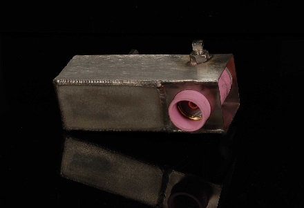
Through many years of experimental trials of trailing shield designs, and failures, the one pictured has been a proven work horse.
About the design: Its modular stainless steel design makes it very easy and convenient to assemble. I have tried several types of stainless steel wool with different size stainless screen mesh with negative results. The rust-less bronze packing within the body welded to the sintered (porous) stainless steel does a remarkable job dispersing the argon flow. It's a cascade effect. You don’t feel gas pressure but you feel flow.
With other screen type designs, argon turbulence tends to cause arc wandering and/or discolored welds. It’s important that the input supply line have a baffle to deflect the flow of argon from directly exiting the trailing shield.
This baffle allows the trailing shield to evenly fill with argon. This promotes equal constant flow of argon to blanket the molten weld pool. Length, width, straight or curved designs depend on type and size of weldment.
The one pictured hereafter is a typical standard 4.38”L X 1.5”W X 1.5”H (111x38x38 mm) design that works well as a universal trailing shield.
The Tig torch attaches to the trailing shield by inserting the #12 Gas cup with gas lens through the body and torch retainer and securing it with a ¼-20 set screw. The trailing shield can be rotated several degrees around the Tig torch for optimum coverage.
Titanium Welding Trailing Shield
PWA heartily thanks Guy Hughson for his kind contribution, showing his expertise on the subject. We believe that Readers could benefit from the information submitted and could possibly gain even more by contacting directly the author. Readers ready to contribute their welding experience with their own notes are encouraged to do so.
12 - Testimonials On Mon Apr 28 05:33:46 2014, the following results were submitted from the "Form 5" on welding-advisers.com: Santosh Pawar
Name: Surya Choudhury Date: 04 May 2014, 05:58:00 AM Hi Elia, The information provided on the website was quite helpful.
13 - Correspondence: a few Comments Among the queries I get, there are occasionally a few widely off mark. This means that I should probably improve the explanations on what information and benefits my website can provide. I shall think this out. I keep receiving Requirements for Quotation, for equipment and materials. It amazes me that certain readers still don't accept that my website is dedicated only to welding information and advice, and is not dealing with actual supply of goods. Other readers asked for trained workforce to help them confronting with backlog. It should be clear that I cannot urgently find welders with specific qualification to work on faraway projects. Several readers ask me for tips on how to find new customers for their job shop, either already existing or yet in the planning stage. I offer my recommendations, addressing them to my various articles that tackle different aspects of the business, but I must admit that my capability to offer serious help in those cases is quite limited, unfortunately. My strength is in other fields, where I can come up with practical help, solving production or repair problems, especially when inquirers don't seem to be alert to the real causes of their hindrances.
14 - Bulletin Board 14.1 - 5th International Conference on 14.2 - Welding Education, Skills, and Certifications Conference. 14.3 - 67th IIW Annual Assembly & International Conference. 14.4 - Heat Treatment Conference
Watch the Video: and also:
BUILT BY:
Click on this Logo NOW! 
Copyright (©) 2014, by Elia E. Levi and
See you next time...
|
||||||||||
| Back to Back Issues Page |