Composite-Die-Assembling
This page describes how to assemble a Composite Die designed according to the principles exposed previously.
See Composite-Die-Description.
1. Manual Assembling
The simplest way to proceed is to assemble manually all the required elements on a working table, without any special tools except a simple manual press (jack type) for pressing the rings (internal and external) together.
The task is clear: to set up the bars stump block within the jaws, and to engage the springs in the pins (inserted in the jaws' holes) as a temporary fixture.
Then the internal ring is slid along the cylindrical surface of the jaws but it is not pushed down to the bottom: it is supported by three equal thickness blocks. Some solid lubricant is smeared on the conical surfaces to facilitate dismantling if necessary.
If there is no intention to prepare a precursor impression on the surface of the composite die one can press down the external ring on the internal one, using the manual press.
One can then remove spring and pins, which are no more needed.
Once the composite upper surface is continuous and complete, one will proceed to carve the impression first by EDM (Electro Discharge Machining) then by CNC milling.
2. Precursor Impression
In case we wish to imprint a precursor impression however, further handling is necessary. It is described in a Note in Section 5 of Composite-Die-Description .
This would remove partially or totally the need to perform pre-machining by EDM and reduce significantly the milling machining time.
Two ways of proceeding have been devised.
The first method uses the fixture as it was assembled above, but before consolidation by pressing down the external ring.
One would need to place it on a hollow support, to permit the stumps to move vertically if pressed lightly upon.
Some trial and error may be needed to squeeze the stumps lightly together but not too much, to allow the push-in to be performed.
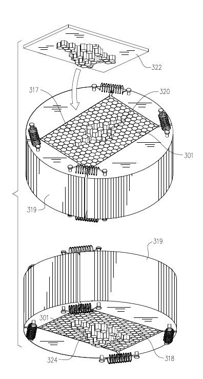
Figure 1 - Use of Punch to imprint a precursor impression
A punch (322 in Fig. 1 above) having the exact profile needed, can be made by 3D printing a suitable plastic block, from a computer program based on the CAD/CAM drawing of the actual impression, on which one would superpose a grid defining the interfaces of the bar stumps.
The program should be able to find out for each bar stump the highest point crossing the final impression surface.
That would define, for each bar stump of the composite die, the required length leaving enough material for milling the final surface.
In the punch however, the length of each protrusion is equal to the difference between the total length of unshortened stumps and the highest point determined above.
It represents the displacement of each bar stump needed to imprint the precursor impression in the loose bar block.
If necessary, another computer program could draw the planar perimeter of the area occupied by the stumps that will be pushed-out by the punch.
A laser beam cutter could cut out of a plate (1-2 mm thick) such an area, leaving a mask, upon which one would locate exactly the temporary fixture.
This helps to keep the peripheral stumps fixed in place, by letting the other ones be pushed out of that plane by the punch.
In order to perform the push out operation one does not need any special tools, only what is available in the shop and some ingenuity to place the punch upon the fixture and push it down gently until the precursor impression is imprinted in the bar stump block.
Then one should press down the external ring as far as it goes using the manual press, upon the internal ring, to consolidate the fixture containing the assembled composite die.
At this point one can remove spring and pins, which are no more needed.
It remains to cut out (by milling, abrasive disc grinding or sawing) the protruding portions of the pushed out stumps to obtain the base of the die, that can be ground flat to get a planar bottom surface.
Alternatively one can provide an automatic set up, where the parts, enclosed in a temporary frame, are pushed out one by one for the calculated length by a computer controlled actuator, as illustrated schematically in the following Figure 2.
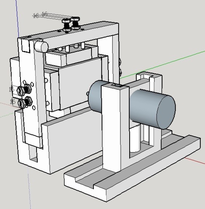
Figure 2 - Computer controlled actuator for pushing single bars
Here again the excess length pushed out must be removed as remarked above.
The second method to assemble manually the composite die so that it will embed a precursor impression, would use the 3D printed plastic tool described above, not as a punch, but rather as a pedestal, an assembling aid.
This tool, that shows the volume filling the impression, presents a number of steps. One should put this tool standing on the work table, with its protrusions pointing up, surround it with the jaws, and fill the space with the prepared stumps.
A magnetic plate may be used to keep the vertical stumps from falling.
It remains to put manually on each of the tool steps a bar stump. Those resting on the tool will be displaced, relative to the base, by the height of the tool in that position.
Once the fixture is consolidated by pressing the external on top of the internal ring and removing the aiding tool (slightly smaller for ease of removal) one has the same composite die as above, including the precursor impression.
Here again one has to cut out (by milling, abrasive disc grinding or sawing) the protruding portions of the assembled stumps to obtain the base of the die, that can be ground to get the bottom surface flat.
Both ways described above produce scrap and include cutting off costs.
Instead of mounting full length bar stumps, displacing them for the needed length, consolidating the fixture and cutting the protrusions, one can put manually on each of the tool steps a bar stump cut to exact length, as indicated in section 2 hereafter.
This operation, to be done manually, needs a system for pairing stub location and stub length.
The beauty of this arrangement is that, if the assembling is done correctly, the top surface of the assembled die will appear plane: any protrusion or hole will indicate a positioning error to be corrected.
Once the assembling is complete and verified, one will mount the internal ring as shown above (on three equal thickness blocks), smear some solid lubricant, mount the external ring and press it down to consolidate the die.
The secondary gain of this assembling method will be sparing the scrap and protrusion cutting costs mentioned above.
2. Other Assembling Solutions
A computer program, similar to that described above, could be used to:
• identify each bar stump in the block (either by coordinates or by a serial number),
• measure the actual length of the stump (not its displacement as before) at the highest intersection of each stump with the final impression surface.
A manual or an automated set-up could operate an abrasive disc cutter placed on a bar feeder to:
• position the stop at the correct length,
• advance the bar to the stop,
• clamp the bar,
• start the motor, move the head to cut the bar, and return to starting position,
• pick up the cut stump and remove burr,
• place it in its position in the assembling bin.
This bar stump block should be manually enclosed into the jaws and consolidated with the ring assembly.
The outermost, hot mounted ring should be put in place after all the previous operations were accomplished satisfactorily.
This concludes the presentation of the assembling methods devised that can be used to build composite dies.
More advanced solutions could be proposed in case there is an interest to explore future possibilities.
An example of numerical stress analysis can be found at
Comments and feedback and further questions are welcome.
Please use the Contact Us Form.
For the Description page click on
Composite-Die-Description.

Watch - The Video:
and also
POWERED BY:
![]()
Click on this Logo NOW!
Copyright © 2016
by Elia E. Levi and
welding-advisers.com, All Rights Reserved.