|
Weld-FAQand the Correct Answers.Solutions with Effective, Practical Advice
This is the first page of Practical Answers to frequent Questions concerning Welding. Your question may have been already answered. The list of Titles of Frequently Asked Questions, is in this first page.
Visit the NEW Page on Welding Overview, for a thorough Introduction to Welding.
Please note that the answers are spread on four pages: Page one (this page): Weld FAQ. Browsing through the list of question titles in this FAQ first page, look for the question you seek. Or, if you prefer, simply go to any one of the three pages and scroll down to see the answers.
Weld-FAQs
Mig or Stick? Process Comparison Welding Titanium to Stainless
Aligning a Long Shaft
Mig or Stick? Q - I am a welder that welds with a lot of different processes. I was told that it should be SMAW welded with E-7018 and not to weld it with Mig. The mig wire we use is ER-70. What is the difference in the two processes? A - Thank you for your question. I feel from it that you are a good, experienced and conscientious welder. One of the disadvantages attributed to Mig (GMAW) when performed outdoors is the possible loss of shielding gas due to the wind: this is possibly the concern of those who "told" you to avoid Mig. It depends upon the circumstances, if suitable wind shields can or cannot be set up. It is accepted that self shielded Flux Cored Arc Welding (FCAW) is less prone to the loss of shielding atmosphere while providing the continuous electrode advantage as Mig does. However breathing FCAW fumes is more dangerous to the welder's health. And of course slag has to be removed between passes and at the end of the process. As far as strength and stability are concerned the design has to be adequate but there are no differences between the two processes that should bother you as long as sound welds are produced. There may be quite a remarkable difference in the cost of welding though, but this is up to the management to decide and be responsible for. What bothers me is that you are made to work in a vacuum of responsibility. About a year ago I wrote an article titled "Where is the Welding Management?" that you can find at As long as your work is good, you will grudgingly get moderate praise (Not too much, lest you may think you are worth a pay raise). If at all possible, you should request from your management precise, written instructions in the form of clear, signed Drawings and Welding Procedure Specifications (WPS). You are not supposed to be "told" anything, you should get only written instructions. Those who give you welding work must take full responsibility in writing for whatever you are requested to perform at the best of your ability, but not any more than that, including process selection.
Q: When and why should Alternatives to Welding be considered? A: Whenever Welding is difficult and expensive and if there is no essential need for the kind of metal continuity provided by welded joints. The main point is that welding processes in general are associated with elevated temperatures. In many situations the application of heat may have adverse effects like crack formation, hardness and strength changes, production of brittle phases, microstructural modifications affecting corrosion resistance properties, unacceptable deformations, alignment and fit problems, introduction of residual stresses. If the risks following the above effects entail the adoption of special procedures to counteract them, then welding becomes a much less attractive solution. Among possible alternatives one could consider the following. Brazing and Soldering that require less heat and may provide adequate properties to the joint. Otherwise Mechanical Fastening, structural Adhesive Bonding, surface modification if effective, elimination of joint by design change. Welding thin to thick Sections Q: A thin tube has to be welded to a thick plate or bar: why is it so difficult to do so? A: The thick element absorbs a large quantity of heat before reaching melting temperature. On the contrary the thin tube melts almost immediately. Therefore to weld properly one has to change the configuration of the joint so that the difference in thickness be kept to a minimum. The bar or plate has to be machined so that at the joint location the thickness be comparable to that of the tube, or an intermediate transition element of proper shape and size must be welded between the two elements. Alternatively, if the joint shape permits it, one should consider brazing or friction welding. Double V-Groove welding of thick Pipe Q: A double-V-groove joint in a thick Pipe requires welding both from inside and from outside. Is there a preference as to which side to weld first? A: Yes, definitely. As the pipe is thick, the process used will most probably be either Gas Metal Arc Welding or Submerged Arc Welding which are both providing high weld deposition rate. In order to guarantee the highest quality the root pass, however being done, has to be back gouged, that is ground for all its length until sound metal is found. This grinding operation with a portable grinder can best be performed unhindered from the outside. Therefore the root pass has to be laid down first from the inside of the pipe. Additional tips: please note that, for longitudinal welds, run out tabs have to be provided at both ends. Furthermore the first weld (from the inside as explained) will start at one end for a length of about 150 mm (6 inches) only. This short weld will prevent distortion and overlapping of the edges under the shrinkage strains caused by the long weld.
Then its inner end has to be ground clean to permit perfect blending with the upcoming weld that will start at the other end of the pipe and proceed towards the already welded short stretch. Once the root weld is completed and backgouged the filler passes will be performed as convenient. EBW Repair of a rejected Casting Q: An expensive finish machined cast aluminum housing was rejected because an internal bore, located deep inside the part, at a great distance below the face of the top flange, was found oversize. How could it be salvaged by repair welding? A: Regular welding would not be an acceptable solution. But Electron Beam Welding a spare bushing in place, although expensive, may salvage the cost already invested in the finished and rejected part. By welding in place a spare sleeve the process has the potential:
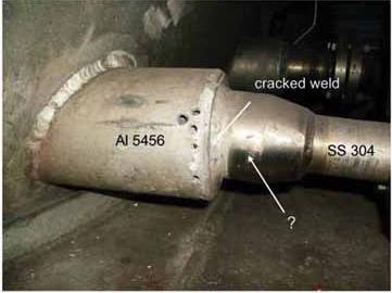
(Note: The above is presented as Example 480 on page 541 of Metals Handbook Vol. 6, 8th Edition). Weld Repair of Aluminum Castings Q: How are Aluminum Castings repaired? A: Aluminum Alloy castings scrapped in the foundry because of surface defects and lack of dimensional integrity can be salvaged by welding except if they present massive porosity. Gas tungsten arc welding (GTAW) with high frequency stabilized Alternating Current is normally used to repair sound castings. Inclusions should be prevented by taking care to avoid touching the surface with the pure tungsten electrode. Argon with or without helium can be used as a shield. Helium helps generating a hotter arc if necessary. To prepare for welding one should remove defects, especially cracks, by dry chipping with a rounded tool or by hand milling, to obtain a smooth area. One should never attempt to weld on the original casting external rough surface without first removing the oxidized layer. Removal of oil and grease is performed using vapor degreasing or clean solvents. Use of acid etch is not recommended. If impregnation was applied, it should be removed before welding. A clean stainless steel wire brush should be used to remove thick oxide layers just before welding. Filler material alloy is usually the same as that of the casting. Preheating is needed only in exceptional cases to overcome difficulties. On suitably prepared surfaces of sound castings, with oxide layers thoroughly removed, one should be able to weld as easily as on wrought alloys. It would be good practice to look for cracks in the weld by using penetrant inspection. Radiographic inspection may be required by contract in certain cases. If the original castings are to be heat treated, also the repaired ones should follow the same process. Weld repairing of heat treated casting would impair their mechanical properties. The feasibility of repair of aluminum alloy castings that were already heat treated and machined is questionable because of stresses and deformations likely to develop during welding. An example of such a repair performed by developing a special procedure with electron beam welding is reported in this page here above under the title "EBW Repair of a rejected Casting". Weld Crack Repair in a Transition Part Q: Al 5356 vs SS 304: would you help me to find the proper filler metal for welding together these two materials? A: The answer to this question is straightforward: Unfortunately the two materials are incompatible, that is they Please see my article: Joining Incompatible Materials But it appears that the question was not formulated correctly. Correct Q: "This is a photo of the joint we are talking about. The equipment is a (liquid) nitrogen tank carrier. I need to repair the cracked weld. Would the reduction pipe be a transition material between Aluminum and Stainless?" A: Yes. The reduction pipe is a transition part obtained made by friction welding together an aluminum and a stainless elements. The aluminum side of the transition element was later arc welded to the aluminum construction, while the stainless part was welded to the stainless tube. As the crack appears to be wholly confined to the aluminum joint, it should be dealt with like a repair in an aluminum part. Conclusion: A misleading question may produce a useless answer.
The Question Mark points at the location of the Friction Welded Joint of the Transition Part, connecting an aluminum element to a stainless cone. Q: How can one keep Submerged Arc Welding Flux in place underneath a joint? A: While performing Submerged Arc Welding of a groove joint from above, in flat position, backing flux is needed also at the underside. To keep it in contact with the surface and to avoid contamination, one can press the flux against the back of the joint by the use of an air inflated hose laying at the bottom of a metal channel full of flux, on top of which the joint is placed. By this method the underside of the root pass remains clean and sound so that little grinding is needed before depositing the next bead from the opposite side of the joint. Out of Position Welding Q: What makes an all position welding rod/wire, 'all position'? What is the difference between this type of rod and the others for flat or horizontal only? A: Covered electrodes (SMAW) for flat and horizontal positions are optimized for maximum weld deposition rate. As such they provide a large but still manageable weld pool that does not run out. Out of position electrodes, useful for vertical or overhead welds, are made with modified shielding cover, designed to control the viscosity of the molten metal to make it more sluggish and capable of adhering to the surface even in overhead position, instead of dripping down immediately. The electrode cover for these electrodes contains elements that affect the wetting of the base metal and the viscosity of the molten weld metal. Viscosity can be controlled also, within limits, by mastering the technique and by adjusting the current. Adequate skill is essential to obtain good and repeatable results. Note that vertical and overhead joints are welded with smaller diameter electrodes than would be used in flat position for the same thickness, with corresponding lower deposition rates. It should be noted that the welding position is an important variable that can affect the weld metal quality. For this reason one should select, whenever possible, the flat position. See also Vertical Welding Tips. Parameters for Welding 1/2 inch plates Q: I've been set a task to find the welding parameters for welding two mild steel plates together using Manual Metal Arc Welding [...] A: We will assume that the plates are to be welded in the flat position, edge to edge with groove joint. The given thickness cannot be welded in a single pass with the process specified, so that the edges are to be machined by selecting one of the two most common configurations. We will refer to the recommendations of a document readily available online, In page 5 of that presentation, beveled butt joints are described:
The joint proposed above is therefore on the high limit of single V joint or on the low limit of the double V joint. U joints will not be considered in this case. What is the difference? Single V joint is welded from one side only. For plates it may make not much of a difference. For a tube or vessel, especially if of limited dimensions, the internal side may not be easily reachable for welding. Double V joint requires more expensive machining, possibly including a new positioning and set-up in the milling machine used. If a flame or plasma machine is available, bevels could be also cut with this equipment. It requires much less weld metal though, about half of it, for purely geometrical consideration. This has remarkable consequences, much less heat input is required and less deformations are generated. For welding from both faces the construction has to be turned upside down (if positioned flat), which may be an expensive exercise for bulky and heavy constructions. The electrode to be used, if special requirements are not imposed, can be E-6011 per AWS classification, that is suitable for AC. The power source for AC is a simple transformer, a quite economic piece of equipment. If other electrodes were selected, welded by DC with more expensive equipment, then Arc Blow (deflection of the arc due to magnetic forces) could become an issue. First, with the plates securely clamped to the weld table, tack welding should be performed. This means short stretches of weld bead, about 13 mm (1/2") long, at some distance from each other, say 100 to 150 mm (4 to 6"). These should be deposited in proper sequence, at distant places to avoid localized shrink stresses. Then tack welds should be cleaned from slag and ground to permit smooth blending of the coming new weld beads. Electrode size depends on operator's skill and preference. It could be 3/32" (2.4 mm) at the manufacturer's recommended current, about 60-80 Amp or 1/8" (3.2 mm) at about 80-100 Amp. The root pass could be performed with backing, if advisable, that should normally be removed after welding. For best quality the root pass should be gouged from the back side and a new pass should be added. Slag of each pass has to be thoroughly removed before applying subsequent passes. Welding speed is strongly operator dependent and should be measured. A more useful parameter is probably the weld deposition rate in weight units per hour. The total number of passes needed to fill the groove depends on the operator technique, if depositing thin parallel beads, or wide beads obtained by weaving the electrode from side to side. Larger size electrodes could be used but at the risk of higher heat input and increased deformation. Three types of deformation should be foreseen and prevented. See the page on Welding Distortion. The first deformation to be prevented is the overlapping of the joint ends as shrinkage tends to close the gap. As mentioned elsewhere, the first weld will start at one end of the joint for a length of about 150 mm (6 inches) only. Then the upcoming weld will start at the other end of the joint and proceed towards the already welded short stretch. The second type of deformation affects the single V groove joint. As the weld metal in the groove shrinks upon cooling it tends to pull in a direction transversal to the joint. The two plates lying flat tend to decrease the angle between them (from 1800 to 170 - 1600 and even less). Imagine a book lying open and flat, slowly starting to close. To prevent this movement one should increase the angle even more before welding, laying the plates not flat but like a roof (say at 2000). With the correct starting angle, welding is going to straighten the plates flat. The third is the longitudinal shrink along the joint which may cause the joint to curve following an arch. This can be minimized by welding short stretches at a time in a proper sequence, that will avoid excessive localized heating, and by peening with a hammer the weld bead while still hot, to introduce compressive stresses to counter the shrinking stresses. Welding a Shaft Q: - I am trying to create a special longer input shaft for car manual 5 speed transmission by welding a newly created, heat treated SAE8620 shaft (HRC58-62) to the gear end section made from heat treated SAE4620 (HRC58-62). Shaft end is SAE 8620 HRC 58-62, (carburized) .025-.035" case depth, quenched in hot oil @ 350F and tempered @300F for one hour. Gear end is SAE 4620 HRC 58-62 with same heat treatment as shaft end. The parts are assembled with light press fit and welded. Samples have been preheated to 300F and TIG welded with 80SD2 filler metal, air cooled with no PWHT (Post Weld Heat Treatment). Using GTAW setup, I need recommendation for pre-weld heating, filler material, and post-weld cooling process. Must be careful not to create cracks or weak areas at weld and must not anneal weldment so as to reduce hardness of gear teeth. Is there a post weld non-destructive quality inspection process? I am modifying existing already hardened input shafts (gear end piece) by welding on new longer shaft end with different spline (26T vs 10T original). I had the shaft end hardened as needed for wear resistance for the clutch to slide along the splined area. A: - Hardness of the two elements is way too high to be suitable for welding. Welding is here a recipe for trouble. If you were to cut a sample part through the welds already done and run a microhardness survey you would find that the surroundings of the weld have been annealed or softened, while the Heat Affected Zone bordering the welds has hard, untempered martensite, which is dangerous in that it can develop cracks if subject to fatigue. In principle it is not good design practice. A non destructive testing could be found, but the proposed welding should not be approved for such a critical application. If you could first weld annealed materials and then carburize, harden, temper AND control Heat Treatment deformations, you might be able to produce a sound part. [Note: There may be an acceptable way out though, if the project is important enough to warrant paying for consultation]
Spatter Reduction in FCAW Q: How can spatter be reduced in Flux Cored Arc Welding? A: For a general overview of this process see our website page on Flux Cored Arc Welding Tips and other pages referenced thereby. FCAW is often perceived as a low cost process, even for Hobby and Home work, in that shielding gas is not required (flux cored wire is self shielded), thus reducing equipment cost and simplifying procurement of consumables. For industrial applications shielding gas (for steel mostly Argon with 8-25 %CO2) is almost always employed, with remarkable influence of the gas mix on the arc and on the resulting welds. It is also claimed to be easier to master than Gas Metal Arc Welding (GMAW), in that only basic skills are required to obtain acceptable welds in all positions. Penetration and deposition rate are higher than for Shielded Metal Arc Welding. The often cited additional advantage is that flux cored filler material, by virtue of special ingredients in the flux can be more tolerant to the presence of rust or mill scale on the steel. The production of thicker smoke and fumes is considered an advantage when welding outdoors because an occasional light breeze would not remove the shielding effect around the weld. It can be a nuisance and a health risk if welding indoors, unless fume extraction is in place to protect the welder. Slag has to be removed in any case after welding and before any additional weld is done on top of the deposited weld beads. When using traditional constant voltage power supplies the polarity selected is mostly DCEP (Direct Current Electrode Positive) that gives a stable arc, low spatter (at the correct voltage), a good weld bead profile and optimum penetration It is important to know which metal transfer mode is used. At lower currents the short circuit transfer mode is operating, usually when welding steel less than 3 mm (1/8") thick. Spatter is best controlled by using voltage adjustment to obtain a crisp, consistent crackle sound. One should learn from practice to recognize the correct sound associated with short circuit welding. As an indication, the starting voltage for short circuit applications with flux cored wire of size 0.8 - 1.0 - 1.2 mm(0.030 - 0.035 - 0.045") is 16 to 18 V. The corresponding wire feed speed could be 1.8 to 10.7 m/min (70 to 420 inch per minute), that would provide 50 to 170 Amps, 65 to 200 Amps, and 130 to 220 Amps for the three wire sizes. If the crackle of the weld consists in a soft plop sound with some spatter, reduce voltage one volt at a time until the correct sound is generated and spatter is eliminated. If on the contrary the sound is harsh and explosive with no soft sounds, then increase one volt at a time until spatter is substantially reduced. With higher current levels the metal transfer becomes the spray mode. Here the arc length should be kept minimal and again one should strive to obtain the consistent crackling sound already described. Voltage for spray mode would preferably be between 24 and 34 V, a good starting point would be 30V. For 1.0 mm (0.035") wire size the wire feed speed could be between 10.7 and 14.2 m/min (420 and 560 ipm) that would provide 215 to 300 Amps for a normal stickout (electrode extension) between 13 to 16 mm (1/2 to 3/4"). For 1.2 mm (0.045") wire size, the wire feed speed could be between 8.9 and 16 m/min (350 and 630 ipm) that would provide between 250 to 360 Amps. Voltage adjustment in spray mode goes in opposite direction relative to short circuit mode. Decreasing voltage (one volt at a time) shortens the arc, but too low a value will bring the electrode to plunge in the weld pool with consequent spatter. Then the voltage should be increased again until the optimum is reached and spatter is substantially reduced. Joining Copper to Steel Q: - We need to TIG weld 3/8" ODx.035" wall copper (SB-75) tubes to a carbon steel tube sheet. We will use Argon gas for shielding, 2% Thoriated Tungsten, would you recommend a low silver (5%) or a high silver (15%) filler metal or something altogether different. Would this be a Brazing (SB) or would this be a Tig (GTAW) process. A: - Joints designed for welding have a shape different from those suitable for brazing. The selection is based upon the function of the assembly in service and on the ease of joining, strongly dependent upon the facilities available and on production quantities, which influence production costs. Please note that ASME SB-75 includes the following materials:
If the joint design specifies butt welding of tube ends, one can Tig weld the tubes with Filler Metal: If the tubes enter into the tube sheet for a suitable overlapping length, depending on service requirements, with clearance on the diameter of about 0.05-0.13 mm (0.002-005") at brazing temperature, one can select a silver based filler metal and a corresponding flux from quite a large list of available materials. For low production quantities an oxyacetylene flame would be adequate. For mass production furnace brazing in a controlled atmosphere would be probably more economic. Cleanliness is always of the utmost importance. Welding Leaded Brass Q: We are welding a cylindrical brass part (60Cu+37Zn+3Pb with approximatively 2% impurities) with stainless steel pipe, by oxyacetylene flame. The Brass part section is 3.5 mm thick where it is being welded and the rest of the part is 8.5 mm thick. Some of the pieces are breaking on the 3.5 mm thickness side. Can you explain what is the reason? A: The stainless steel pipe should be of the weldable type, not prone to sensitization, otherwise it could become easily corroded. See our page on Stainless Steel Welding. The filler metal and the flux used were not specified but this is not the main thing. However the fusion process selected is not suitable for the application, because lead (Pb), added for improving machinability, causes the brass to become hot-crack susceptible upon welding. Therefore this alloy should not be fusion welded. If arrangements can be made to produce overlapping joints with small clearance, brazing could be performed instead of welding, with silver base alloys. See our page on Brazing. Otherwise substitution of the said copper alloy with unleaded brass should be considered.
Q: What shall I use to weld stainless steel? A: This question, which I actually received from a reader, is unfortunately not sufficiently defined: therefore it is not possible to give a meaningful answer. One must first describe a few parameters to qualify the solution requested. Material: as explained in another page on Stainless Steel Welding (opens a new page), there are many different types of steels loosely responding to this category, but they can be grouped in four or five families having important characteristics in common. Each family/type has to be addressed separately as they behave differently during welding and need specific instructions. Therefore, before tackling a job, one has to know positively or to have analyzed qualitatively the stainless steel type involved, for identifying at least its family. Joint: type and dimensions of the needed joint must be stated. One should pay attention to the deformations that may develop as a consequence of welding and take proper precautions. Process: If we think of a small shop and of an occasional job coming up once in a while, we will try to adapt whatever process is available that will give an acceptable solution. If we have a larger shop with plenty of equipment to choose from, and with experienced workforce with the needed skills, we will be able to select in complete freedom. If we are planning for mass production we will be able to purchase the equipment capable of the most cost effective welding. Consumables need to be suitable both for base material and for process selected. Of the common processes that can be used to weld stainless steels we will consider only three:
One should note that the old time Oxyacetylene Gas welding process, requiring the use of fluxes for removing the oxidized layer, should not be considered for quality welds. Filler metals for stainless steels are briefly introduced in an article in Practical Welding Letter No.02 for October 2003, visible by clicking on PWL#002. Standards for stainless filler metals are listed in the page on Stainless Steel Welding indicated above. Welding Stainless Handrails Q - I had a contractor install handrails on the stairway. A - Assuming that your contractor installed austenitic stainless steel type 302 or 304 handrails, and assuming that the filler rods were correct (should have been type 308L or 347), there is nonetheless the question of sensitization as explained in my page It appears that the contractor either did not know or did not care. He should have looked for base material type 304L or 321 to avoid the corrosion problem in the first place, with the above filler material. If the corrosion is concentrated at the joints, to mask it you may possibly paint with aluminum pigments paint, but you may need to repeat painting frequently. Welding Stainless to Nickel Alloy 600 Some recent queries asked for information on welding stainless to nickel. As the queries did not specify the request in more detail, given the rich variety of stainless steels and also the different types of nickel base alloys available, this note will refer to austenitic stainless steels and to nickel base alloy 600. The following indications may provide some orientation but one should keep in mind the service conditions and check if the proposed filler metal selection is suitable to the applications considered. You may wish to see also our page on Welding Nickel that includes two tables of Filler Metal chemical compositions, and also a short note on Filler Metals for Welding Nickel published (4) in the Practical Welding Letter PWL#062. For the dissimilar welding of austenitic stainless steel to nickel alloy 600 the following filler metals are recommended. Welding Electrodes per AWS A5.11:
Welding bare rods per AWS A5.14:
Stainless to Mild Steel Welding Q: Is it possible to Arc weld Stainless Steel to Mild Steel? A: Yes, Austenitic Stainless Steel is currently welded to Mild Steel, with certain precautions. First, the Stainless should be of a composition not susceptible to sensitization otherwise its corrosion resistance properties will result impaired by welding. (See on this problem the article in the Welding Advisers Site, Click on Welding Stainless Steels .) Second, especially if the mild steel element is thick, it is customary to weld on top of it a layer of stainless (Type 309 or type 312) or of high nickel filler metal: this procedure is called buttering. The final welding thus occurs between two stainless surfaces. Note: - The above answer is correct only if the service conditions of the assembly are at room temperature. Brazing Carbon Steel to Stainless Q: How one brazes carbon steel to stainless steel? A: There are different considerations and precautions that have to be taken into account, depending on actual configuration and joint details. Also production quantities will dictate the most economic assembly and heating methods. Nevertheless different basic characteristics for the two base metals above need always be accounted for. Coefficient of Thermal Expansion: if a metal with higher thermal expansion (like austenitic stainless) is the outer part of the joint where the inner part is a lower expansion metal (like carbon steel), clearances that are correct for allowing capillary flow at room temperature become excessive at brazing temperature. Interchanging the materials in the same configuration (outer in place of inner material) risks to close the gap at all at brazing temperature: this should be avoided. Thermal expansion differences should be known and used to obtain the correct gap at brazing temperature. The brazing filler metal must be compatible with both base metals: this generally means that no brittle intermetallic compounds should be formed. If corrosion or oxidation resistance is needed, the properties of the filler metal in service conditions should be known. In the proposed combination above, the stainless material (depending on the actual type) has some corrosion resistance to atmospheric exposure, while the carbon steel, lacking it, must be provided with a suitable protection (oil, paint or plating). Galvanic couplers susceptible of promoting crevice corrosion, should be avoided. The ferritic, non hardenable stainless steel type 430 is known to be subject to interfacial corrosion when brazed with most silver based filler metals. A special silver base brazing filler metal containing nickel and tin, AWS BAg-21, was developed to avoid corrosion with this material. Thorough cleaning of the elements is required as usual before brazing. Depending on the heat application method used, a suitable flux may need to be applied because heating in air develops surface oxide that interferes with brazing. For austenitic stainless steel (300 series type) many fluxes are suggested as suitable, differing in the activity temperature range, typical ingredients and form (liquid, powder or paste). See AWS A5.31 - Specification for Fluxes for Brazing and Braze-Welding. Fluxes are available as commercial brands. One should select and test a product compatible with the filler metal selected and, in the case above, suitable for all brazeable ferrous metals (except those with aluminum or magnesium). Of the different brazing filler metals available, the ones based on silver have lower brazing temperature than those based on copper and should be preferred whenever possible. Stainless to Cast Iron Welding Q: How can one weld austenitic stainless steel to gray cast iron? A: Much depends on the configuration of the intended joint, on the thickness and
constraints and on the process being used. Assuming that the SMAW (Shielded
Metal Arc Welding) process is used, one should first clean and preheat the cast
iron. Then one should deposit on it a buffer layer either of stainless steel (type 309 or 312) or
of nickel base alloy (ENi-CI). This procedure is called buttering. The main concern is avoiding cracks. The technique should concentrate in melting the minimum of base metal, by
introducing the least amount of heat, with the smallest electrode and the least
current, with thin weld beads. The weld is built up with additional beads (after
slag removal) until finished, without cooling down. Finally the austenitic stainless steel is welded to the buffer layer. Slow cooling down to room temperature is obtained by providing insulation to the cast iron or by cooling in a furnace. An interesting supplement to the above presentation was published in a note by Damian J. Kotecki, Technical Director at the Lincoln Electric Co. and President of AWS, on page 14 of the March 2006 issue of the Welding Journal. It is reported that, due to dilution with high carbon Cast Iron, weld metal from 309 or even 312 stainless steel electrode risks cracking because the composition of the deposited root pass layer results without any ferrite. Even if cracking is avoided by suitable preheating, both the weld metal and the Cast Iron heat affected zone result rather brittle. The problem stems from the carbon in the Cast iron combining with the chromium in the stainless (309 or 312) to produce, in the resulting weld metal, networks of eutectic chromium carbides in austenite. A better suggestion would be the use of electrode ENi-CI per AWS A5.15. Due to the complete absence of chromium from the composition of this last electrode, significant chromium carbides will not be produced. Furthermore this electrode would promote spheroidal graphite formation in the nickel base alloy, and also lower hardness results in the weld metal. However, even if cracking during welding is avoided, there is still the danger of cracking being produced later by shock loading due to the intrinsic brittle nature of the boundary layer.
Cast Iron to Mild Steel Welding Q: - How should one weld Cast Iron to Mild Steel? A: - Cast Iron is an alloy of iron, carbon and silicon. Other elements may be added for special purposes.
The mild steels to consider should have limited content of Sulfur and Phosphorus, which are known to contribute to hot shortness or the formation of cracks at the time of solidification. Cleanliness and weld preparation is always most important. It is known that welding might produce brittle structures and in general reduce the mechanical properties of cast iron. However successful welds can be performed for useful purposes if one acknowledges the limitation introduced by the processes. A successful welding process should not cause the formation of cracks during or after welding and should not introduce harmful or excessive residual stresses. There is not a single welding process capable of welding successfully any conceivable combination of iron castings and steel. Furthermore one cannot point to a single filler metal rod or electrode to cover all possible cases. Therefore the problem is not simple. Furthermore small iron castings behave differently than large and massive cast pieces. The mass has a great influence on the self quenching capacity of the parts and on the cooling rate after welding, directly affecting the obtained structures. Any welding process produces two zones that undergo important structural transformations:
To control the properties of the heat affected zone, to reduce hardness and shrinkage stresses, one has to reduce the cooling rate. This is usually achieved by preheating the iron casting, either locally with a flame, if it is very large, or preferably in a furnace. And then, after welding, by letting it cool slowly, having wrapped or buried it into insulating material, or again in a furnace. Preheat will also control the structure of the weld metal itself to the point that the formation of martensite is minimized or avoided at all. However, small castings can be welded sometimes without preheat if the results are acceptable. Alternative techniques consist in welding thin and short beads. Subsequent beads temper the hard structures generated by previous ones. To reduce and redistribute residual stresses, peening of the still hot bead with a rounded ballpeen hammer should be performed. Further weld passes contribute to interpass heating that helps in preventing too rapid cooling. In general one should try to heat to the least possible peak temperature, to introduce the minimum heat, using small electrodes and low currents, to apply suitable preheat, to control interpass temperature and to study the performance of different types of filler material until the satisfactory selection is found. The consumables available for welding cast iron are quite varied. Filler Metals of different types can be used for welding cast iron to mild steel. The selection should be based on ease of performance and on the acceptable results achieved. Once the main factors are understood and taken care of, practice and trials can tell which is the most economic and best solution for any particular case. When using SMAW, the steel electrode (ESt) will give a very hard weld, non machinable, useful only for very small repairs. Standard low hydrogen electrodes like E7018 have been used successfully, provided they were dried thoroughly to minimize moisture content. Even iron powder containing electrodes like E7024 were employed with good results. Cast Iron electrodes (E-CI) with about 2.0%C, provide a structure similar to that of gray cast iron: the weld metal is likely to harden unless proper provisions are put in place. For difficult cases conducive to cracks, using Ni-Fe electrodes (ENiFe-CI or ENiFe-CIA) with about 50 %Ni- 50% Fe is probably the best selection for the dissimilar welding of cast iron to mild steel, although not the most economic. If a more ductile or machinable weld must be obtained, high nickel electrodes (more expensive) can be tried, like ENi-CI or ENi-CIA, that will result in a soft, ductile and machinable deposit. If a more strong weld is needed, for example for nodular irons of elevated mechanical properties, ENiFeMn-CI can be used, where the addition of manganese improves strength, ductility and resistance to cracks. The electrodes included in the AWS Specification A5.15 are not the only ones available. Proprietary electrodes, not classified with AWS, are available with improved properties for special applications. In difficult cases it may be worth to seek advice from electrode manufacturers, to experiment and to check results. For certain production lines, higher deposition rates than those available by SMAW (with covered electrodes) may be preferable. In these cases GMAW (Mig) has been applied successfully, especially for ductile or malleable iron. The wire composition is similar to that used with covered electrodes. Steel wires of types ER70S-3 and ER70S-6 have been used and also ERNiFe-CI. Also nickel containing wires (high nickel, nickel-iron, nickel-iron-manganese) are being used. All other precautions should be in place as necessary. This presentation would not be complete without including also the solutions that employ the oxyacetylene flame. The slower heating rate of this process causes a larger heat affected zone to form but effectively avoids the development of brittle martensitic structure. Consumables are cast rods with higher levels of carbon and silicon than the castings. RCI, RCI-A and RCI-B are used respectively for gray cast iron, higher strength alloyed iron, and for malleable and ductile iron. Suitable fluxes must be used to protect the molten metal from oxidation. Preheating must be provided. Slow cooling must be ensured. Besides welding, in certain cases it would be useful to consider also braze-
welding as a possible solution. See Braze Welding.
Repairing a Crack in Cast Iron Q: How is a Crack repaired in a gray Cast Iron? A: A special section addressing this question has been included in the Welding Advisers Site. Click on Welding Cast Iron. Q: Can an AISI 1141 cold drawn rod be welded to an ASTM A572 Gr.50 plate? A: Fusion welding should not be attempted. AISI 1141 is resulfurized for increased machinability (free machining). Sulfur causes hot shortness producing cracks. In certain cases it could however be friction welded, if strength requirements are limited. Welding of 1018 to 4140 Q: - How is 1018 welded to 4140? A: - Welding 1018 to 4140 is possible although one should know more about the application, because the differences between the two steels may cause consequences one may not want to get. 1018 is a mild steel weldable without problems and not hardenable except by diffusion surface treatments like carbonitriding which need not concern us here. 4140 is a chromium molybdenum low alloy steel with medium carbon content (about 0.40%) that can be hardened by direct quenching and tempering. It can be welded but with special precautions like preheating, to slow down the cooling rate. Without preheating, fast cooling after welding generates martensite, a hard structure that risks to develop cracks near the weld. Welding a soft steel to a hard steel can be useful in certain cases, for example if a handle needs to be joined to a hard implement. One should understand that the handle will not become stronger, and that the implement, if it was heat treated to a high strength and hardness before welding, will become weaker near the weld, because of the heat. Two contrasting things will happen because of the localized heating of welding. On one hand all the volume heated, next to the weld, to a certain temperature up to the so called transformation temperature (say up to about 750 0C or 1400 0F) will become weaker due to annealing, effectively eliminating the higher properties due to heat treatment. But very near to the weld itself, the temperature will exceed the transformation temperature. The material structure will change into "austenite", hardenable upon cooling once the welding process is stopped. Not only will the material become very hard in a thin strip near the weld, it might also crack. Suppose we can preheat with an oxyacetylene flame and that we want to weld by SMAW (or stick) with an electrode of almost any usual type. If we know what to expect, that our mild steel handle at the weld will be weaker than the hardened implement, and if this is OK for the application, we should heat with a flame, before welding, the 4140 implement where we want to place the weld. By so doing we avoid cracking. The full hardness of our implement will still be present in the part at some distance from the weld (say at 50 cm or 2", depending on thickness, on the size of the weld and on the amount of heat input). We should again heat the weld with the flame, to temper or soften any martensite that could have formed in the process (Local Stress Relief).
Welding a splined End onto a hardened AISI 4140 Shaft Q: How do I weld a splined end to a 4140 shaft hardened to 28-32 HRC? A: The best process would be Friction Welding.
But some of the length is consumed, and flash has to be removed. Q: How can an appendage be welded to an implement made of stainless steel 440C? A: It cannot, because 440C is not weldable. One can select a different solution:
Q: We need to attach a .080" thick 1045 sheet stock part to a hardened part (RHC 58-62) that has a bearing race on it. The preferred material for this part is 440C. A corrosion resistant material is needed. The weld joint is a slip fit at this time with fillet welds on one side and seam welds on the other. Can Hardened 440C be welded successfully to a dissimilar material? A: No. Unfortunately 440C is unweldable. We already treated this matter. As the material 440C, a very hard stainless steel, cannot easily be replaced, one has to look for an alternative joining method. Given the slip fit of the assembly, it seems that the best solution would be adhesive joining. The adhesive and the clearance have to be selected with care, following adhesive manufacturers' recommendations. Q: How can tools made of nitrided tool steel be repair welded? A: Nitrided layers should first be mechanically removed, for a depth at least the double of their original nominal thickness. Then welding can be attempted but its quality may be questionable because of diffused nitrogen even deep in the tools. For information on Welding of Tool Steels click on Welding Tool Steel.
NOTE - Additional answers appear in the second and in the third page of Weld-FAQ, but are reachable by clicking on the titles of the list at the top of this page or directly from:
Any questions or comments or feedback? Write them down and send them to us by e-mail. Click on the Contact Us button in the NavBar at top left of every page. PAST ISSUES of Practical Welding Letter can be found at the:
Welding Overview Friction Welding Processes
If you did not yet find what you need, why not typing your question in the following Search Box?
Scorpion
POWERED BY:
Click on this Logo NOW! Watch - The Video: and also
Copyright (c) 2004-2009, 2010, 2011, 2012, 2013, 2014, 2015, 2016, 2017 Answers to Frequently Asked Questions illustrate from a practical point of view the aspects that must be kept into focus for successful application of welding knowledge.
|