Composite-Die
This page illustrates a new
METHOD OF CONSTRUCTING A COMPOSITE FORGING DIE,
OR FORMING DIE.
1. Anticipated Advantages
The following anticipated advantages are at the origin of the new method of building Composite dies, described in this page:
- Providing economy of material and reduced machining time,
- Eliminating wasted lead time waiting for raw material,
by preparing a stock of standard bars for any future die, - Using prehardened, simple, inexpensive tool steels,
- Disposing of costly special tool steels,
- Saving on needless heat treatment of machined dies,
- Implementing Robotic assisted special assembly to prepare Precursor Impressions,
(See Note in Section 5 further down this page.) - Eliminating or reducing the need of Electro Discharge pre-machining (EDM).
Different ways to obtain such temporary approximate impressions and Robotic assembly methods that will speed-up fabrication are being explained in our page on
Composite-Die-Assembling
(See link further down this page.)
2. Comparing Costs
Assessing the benefits of constructing composite dies to realize the advantages listed above for certain suitable classes of selected dies should be based on educated guesses.
Complete economic comparison should wait until practical experience is gained with the production of simple composite dies.
3. Comparing Performance
When designing dies one should first obtain simulation of the operating stresses in the constraining members by means of numerical analysis.
In a simplified simulation (see link) performed by a stress Engineer on a similar composite die design, the stresses in the constraining elements were found to be well within the values acceptable for construction steels.
The design of these new dies should provide performance results fully comparable to those of traditional monoblock dies.
Additional means, if necessary, are available to improve stability.
For exceptional requirements, to improve performance, some form of interlocking of the bars among themselves can be proposed.
4. Description
Fig. 1 shows an assembly view of a forging die with the impression of an item to be forged as an example.
The item has the shape of half a sphere connected to two half cylindrical arms.
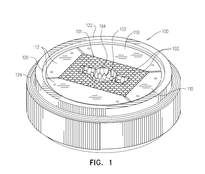
Fig. 1 - View of the die assembly
The working part of the die is made of an assembly (101 in Fig. 1) of standing bar stumps of identical hexagonal cross section (102) (except for some bars of the outermost lining), constrained in a complex tool designed to sustain the centrifugal compressive forces operating on the die while forging the heated steel chunk into the impression.
The constraining tool is made of a few elements.
Four hardened tool steel jaws (110 and 112 in Fig. 1) contain the block of standing bar stumps.
Their internal vertical faces press on the bar sides or sections.
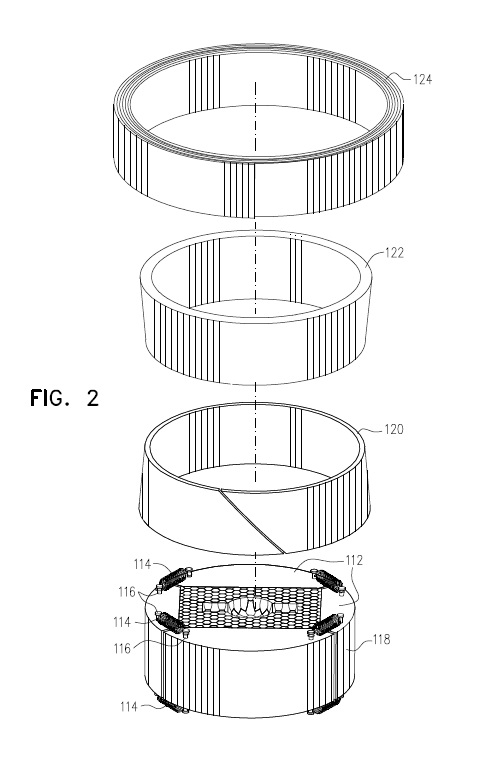
Fig. 2 - Exploded view
The composite external surface of the jaws is cylindrical.
Embracing this cylindrical surface is a hardened tool steel internal ring (120 in Fig 2).
Its innermost surface is cylindrical, to enclose the jaws assembly.
Its outward surface is conical, and a single cut splits this ring, to allow some elasticity and movement.
A hardened tool steel external ring (122 in Fig.1 and in Fig. 2) has a cylindrical external surface.
Its internal surface is conical, conforming to the slant of the internal ring.
After sliding the external on the internal ring and pressing it down with a simple hand driven press, significant centripetal pressure is applied on the assembly included thereby.
To provide an even more consistent constraining force, needed to stand the severe forging blows, an outermost ring (124 in Fig.1 and in Fig. 2) is provided.
It is built by wrapping tightly a thin steel band around a collapsible wooden cylindrical form.
To ensure its stability, short stretches will be welded between adjacent band layers on its top and bottom surfaces.
The internal diameter of this last ring and the external diameter of the wooden form are about 1.4% smaller than the external diameter of ring 122.
The collapsible wooden form is needed to free the steel ring after wrapping it around the form.
This steel ring is designed to be assembled on the composite die after being heated in a furnace, to encircle ring 122 and to develop significant constraining force by interference fit when shrinking upon cooling down.
A thin layer of wear resistant thermal sprayed deposit applied on the finished die impression surface is intended to reduce surface wear and to fill interface clefts.
5. Material Type, Shape and Size
This design of Composite Die confers ample freedom to select type of steel, shape and size of basic elements, to be most adapted to the final use.
The bars shall be made of hardened tool steel.
The type of the tool steel is open to study and to test: it is anticipated that simpler and cheaper tool steels (than in typical monoblocks used for die making) can be used, as sufficient hardness can be obtained with regular heat treatment, due to bar small size.
It is assumed that the change of material would provide the opportunity for significant economy.
As indicated above, the cross section of the bars of the block in the example illustrated above is hexagonal, except for some of them that were cut axially along two different planes (one through two opposite corners, the other through the middle of two opposite faces).
The hexagonal shape is by no means the only one to be selected.
Square bars bay be simpler, provided there is no danger of chipping at the corners, that may result fragile.
Rectangular bars may also be considered.
In principle the type of geometric figures suitable for building dies by this method is limited only by the requirement of tessellation, that is that the plane be filled like by tiles on a floor without leaving unfilled spaces.
If a practical need will arise for assuring stability of the configuration beyond that given by the constraining means
provided by design, some form of interlocking of the bars among themselves can be proposed.
For assuring tight and consistent tolerances it is probably preferable to specify drawn bars.
The size of the bars can be selected depending on design and availability.
It may also depend on the type of die to be made.
The smaller the size, the higher the definition of details achievable, and probably the machinability in hardened condition, but the number of bars in the block will be higher. The optimum will be a compromise, reached with accumulated experience.
Note: a precursor impression is an approximation of the final impression to be machined on the die surface. See Fig. 3
It is obtained by assembling in selected locations, determined by a computer program, bar stumps shorter than those defining the free, top surface of the die.
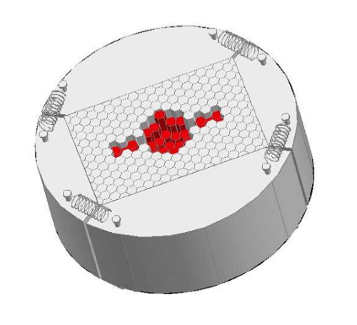
Figure 3 - Precursor Impression
6. Conclusions
It is assumed that every Enterprise, wishing to test the idea more in depth, will select the types of dies of their production lines likely to profit the most of the new construction method.
This method opens up the possibility to test simple tooling prototypes before committing extensive resources to build complex dies. Or to explore the making of simpler interchangeable inserts in more elaborate monoblock dies.
The Composite Die design, described in this page is covered by a pending patent, submitted in the name of myself, Elia E. LEVI, to the
UNITED STATES PATENT AND TRADEMARK OFFICE:
APPLICATION NUMBER: 15/012,706
FILING DATE: February 04, 2016
Further elaboration on Assembly techniques can be found at:
The simulation example is shown at:
Comments and feedback and further questions are welcome.
Please use the Contact Us Form.

and also
POWERED BY:
![]()
Click on this Logo NOW!
Copyright (©) 2016, by Elia E. Levi and
www.welding-advisers.com
All Rights Reserved