|
Power-Sourcesfor Arc Welding: Types and Classes.SOLUTIONS with Effective, Practical Advice
Power-Sources or supplies generate and maintain the electric arc. Arc welding processes use specific equipment and consumables. The arc provides the localized heat needed to perform progressive welding. Power-Sources obtain their input from the power grid, and output their energy in usable and controlled form. Power Sources for Arc Welding transform the power from the grid to controlled values of voltage and of current suitable to the intended uses. This modification is required because the characteristics of the utility energy supplied are not suitable to establish the electric arc needed for welding. For most of welding purposes, welding voltage ranges from 20 to 80 volts (V) and current (with the exception of micro welding) from 30 to 1500 Amperes (A). Welding processes use direct current (dc), alternating current (ac) or pulsed current. Power-Sources are generally classified as constant current, constant voltage and waveform control or pulse welding. That qualifier (constant) must be understood as a useful simplification, not as an absolute value. The relationship is expressed graphically in a static volt-ampere characteristic diagram. More advanced Power-Sources with dedicated electronic devices can reach higher levels of control. Then the output is truly constant, generally supplied in pulses over a range of frequencies, as required for special applications. The common welding arc processes are:
The type of current and voltage must be suited to the arc processes considered. But also
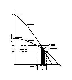
Figure 1 represents such a diagram for a typical constant current welder. Two volt-ampere curves meet at a given welding set point. The vertical axis is for volt values while the current is represented by the horizontal axis graded in amperes. A constant current power supply will show gradual current increase with decreasing of arc length and arc voltage. This kind of Power-Sources is generally used for manual welding processes as SMAW, GTAW and PAW.
The steeper curve starts from the highest maximum open circuit voltage (OCV). The less steep curve starts from the minimum OCV. It should be remarked that the no-load or Open Circuit Voltage is always much higher that the actual voltage drop across the arc. The dark area represents the change in current consequent to a change in voltage on the steep curve. One can appreciate that on this curve the current would change not much (~constant) within the borders of the dark area. The selection of the highest open circuit voltage, and consequently of the steeper curve, would allow minimum current change for relatively important voltage excursion. That is advantageous for out of (flat) position welding with small size electrodes.
In manual welding the actual voltage across the arc is determined by the arc length as established by the manipulations of the electrode by the welder. The welder can easily reduce the current by increasing the voltage across the arc. That is done, when risking to blow the weld by too much heat, by lengthening the arc length (pulling somewhat the electrode from the work). Conversely, by operating the power source upon selection of the lower OCV (flatter curve) the same voltage change as before would produce a more significant current variation as indicated by the larger current interval. This could be advantageous when welding with large electrodes in flat or horizontal position. By shortening the arc length, the welder can thus obtain more current and more heat input. That would provide higher deposition rate (and vice versa).
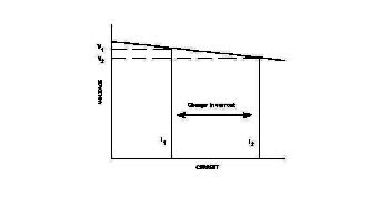
Figure 2 shows the diagram for a constant voltage power source, representing that a slight but measurable voltage decrease corresponds with current increase.
This is the typical output used for dc GMAW, SAW and FCAW, where a continuous electrode in wire form is fed into the weld pool. If the wire is fed at constant speed in an automatic process, the system is self-regulating. In fact if the voltage decreases, meaning that the torch is momentarily farther away from the work, the feed and the current tend to increase. With increased current increases also the electrode melting rate, restoring arc length and voltage near to the set point. Arc Current is proportional to feed speed. Using electronic controls it has been possible to design Power-Sources combining in a single unit both characteristics selectable at choice. Either constant current or constant voltage, depending on the welding process at hand. Small Power-Sources (80 to 250 A) with single phase ac input and output are available for users with limited requirements. Those may be small welding shops, schools, hobby shops, rated at a 20% duty cycle (see further down). Slightly larger (175 to 350 A) single phase ac input may have selectable ac or dc output, with additional controls useful for GTAW. For industrial applications and greater current requirements, most Power-Sources have three phase input. Output characteristics are suitable for selected processes as needed. The third class of Power-Sources is that delivering waveform controlled or pulse welding output. That is achieved with modern electronic controls, especially from inverter supplies (see below). Electronic controls permit to manipulate the welding current in pulses whose characteristics are fully specified. Each parameter can be selected in turn, or predetermined optimized programs saved in computer memory can be run. Among the most important control parameters are:
The program selection takes into account:
The versatility of waveform control is a major achievement of power source developers and manufacturers. To enable the exploitation of such advanced capability however, the personnel in charge of utilizing the sophisticated equipment must have sufficient training. They should get also the opportunity to develop experience by trying, testing and collecting results. Otherwise the over-choice risks to cause only confusion. A major progress was achieved with the introduction of inverter based Power-Sources. They are smaller, lighter and much more efficient. AC input from the line grid at 50 or 60 Hz is rectified to dc. A solid state device circuit converts dc to high frequency ac in the range of 20 to 100 kHz. Voltage is then reduced with a step down transformer and then output current is rectified and smoothed for arc welding. Duty Cycle Besides the maximum current rating, an important limiting factor to be taken into account when selecting a definite Power Source is its Duty Cycle. It represents in percentage, the amount of time in any 10 minutes averaging interval, when the source can deliver its maximum rated power without overheating. The off time is needed to allow cooling down of the sensitive elements to a safe temperature. Equipment intended for continuous operation should be capable of delivering the rated maximum output at 100% Duty Cycle. For welding in locations not reached by the electric power grid Power-Sources are used that take their energy from prime movers such as internal combustion engines. Two types of rotating machinery are used that supply power for arc welding. Generators produce direct current and Alternators provide alternating current. The final supply type however, can be further transformed by suitable means to meet requirements. But it is not as simple as that. Both generators and alternators convert rotary mechanical energy from a gasoline or diesel internal combustion engine into electrical power. The rotating part is called the rotor, and the static part, generally external to the rotor is called the stator. Electric current is generated when conductors move relative to a magnetic field, but it is irrelevant which moves and which is at rest. In principle a generator has a stationary field and moving conductors, and provides direct current, whose shape is obtained by mechanical rectification. This means that the power produced is collected at the rotor end through a commutator consisting in a group of conducting bars making a switching contact with a set of stationary carbon brushes. The shape of the voltage is therefore the positive half of a sinusoid repeated identically along the horizontal coordinate. An alternator has moving magnetic field coils on the rotor, and stationary conductor power coils on the stator, from which the current flows. The electric power from engine driven units is however transformed as needed to be readily employed for welding (with well defined characteristics for each machine) and also for auxiliary power for home or shop use. Manufacturers advertise that the welder comes as a bonus included, as the cost of the complete unit is comparable to that of a separate generator alone. I could not find definite suggestions for selecting either a generator or an alternator depending on welding needs. To study a sample of different engine driven Power-Sources with integral welders, one can see parts of this catalog (no endorsement or recommendations intended): The following document provides information and assistance to those confronted with the task of evaluating candidate equipment for specific applications. NEMA EW 1-1988 (R2004) The three classes of Power-Sources established by NEMA are as follows:
In conclusion, for selecting suitable Power-Sources for Arc Welding one should try to define with maximum thoroughness the actual welding needs by identifying the processes to be supported and the ranges to be covered. If possible one should try to put the selection at test by leasing it for use before final decisions. An Article on Advances in GMAW Power Sources was published (7) in Issue 154 of Practical Welding Letter for June 2016. An Article on Feedability of Aluminum Filler Metal in GMAW was published (3) in Issue 155 of Practical Welding Letter for July 2016. An Article on Pulsed GMAW was published (3) in Issue 163 of Practical Welding Letter for March 2017.
To get at no cost every issue of Practical Welding Letter as it is published, please subscribe.
If you did not yet find what you need, why not typing your question in the following Search Box?
Artwork for Hobby
Any questions or comments or feedback? Write them down and send them to us by e-mail. Click on the Contact Us button in the NavBar at top left of every page.
To reach a Guide to the collection of the most important Articles from Past Issues of Practical Welding Letter, click on Welding Topics.
Tig Welding Tips
Watch the Video: and also:
 Follow this Invitation! Experience C2 power and flexibility in action by checking SBI! 2.0 For You. BUILT BY:
Click on this Logo NOW!
Copyright (©) 2012, 2013, 2014, 2015, 2016, 2017 
|